

Tabla de Contenidos
Noticias relacionadas
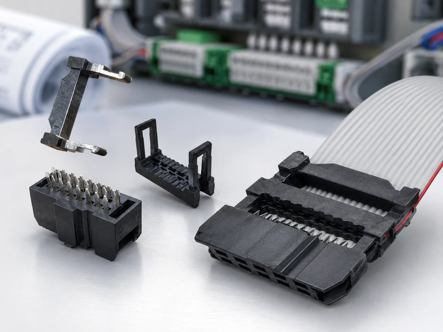
Pruebas de mazos de cables antes de la producción en masa: continuidad, fuerza de tracción y ajuste.
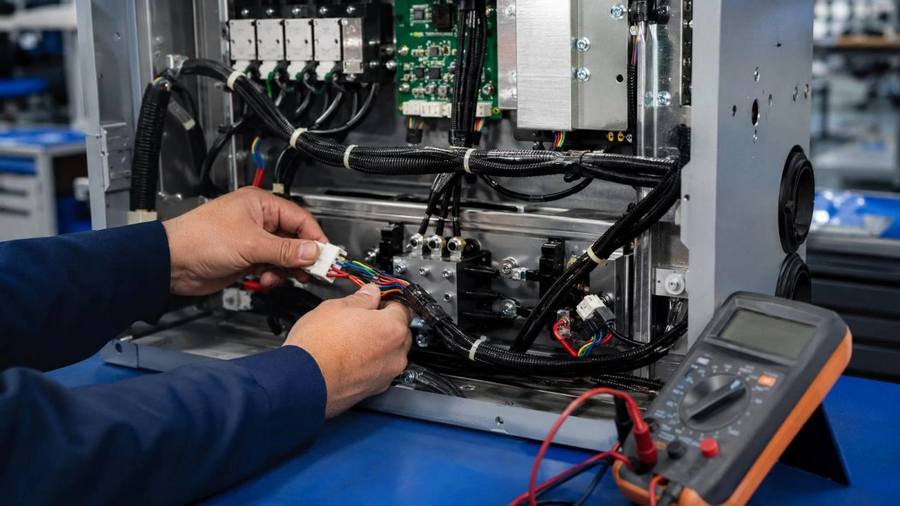
Las pruebas de cableado previas a la producción en masa deben demostrar algo más que si una muestra se enciende o supera una prueba básica de continuidad. Un prototipo puede funcionar en el banco de pruebas, pero fallar tras la instalación porque un terminal se suelta, un pestillo queda abierto o la longitud final ejerce presión sobre una conexión. Una sola prueba no puede detectar todas estas fallas.
Una muestra funcional demuestra que una unidad puede operar. Sin embargo, no prueba que el conjunto de cableado pueda fabricarse, instalarse e inspeccionarse de forma consistente en un lote de producción. La aprobación debe responder a tres preguntas: ¿Es correcto cada circuito? ¿Se mantendrá segura cada terminación? ¿Cabrá el arnés completo dentro del equipo?
Por qué una muestra funcional aún no está lista para la producción en masa.
La funcionalidad eléctrica es solo el primer nivel de aprobación. La continuidad puede demostrar que la corriente puede circular, pero no que el conductor alcance el terminal previsto. Una prueba de tracción puede mostrar que un cable permanece conectado, pero no que el contacto esté bloqueado dentro de su alojamiento. La longitud final puede coincidir con el plano, aunque el arnés aún bloquee un pestillo.
Por lo tanto, para su liberación se requieren comprobaciones eléctricas, de retención mecánica y de ajuste. Cada resultado debe corresponder a la misma revisión del plano, especificación del terminal, especificación del cable y muestra aprobada.
El control de producción de cables distingue entre conexiones incorrectas de pines, mal contacto, desprendimiento de terminales, daños en el aislamiento y fallas de blindaje, ya que cada una requiere una acción correctiva diferente. La inspección final puede incluir la continuidad de los pines, la resistencia de contacto, la integridad del aislamiento, pruebas de tracción y registros trazables.
Puerta uno: Verificar que cada circuito sea el circuito previsto.
La inspección eléctrica debe confirmar que todas las conexiones existen y que cada conexión cumple con la función que se le ha asignado.
Una prueba de continuidad confirma una ruta, no su propósito.
Una prueba de continuidad permite identificar circuitos abiertos y, con el dispositivo adecuado, conexiones no deseadas. Es útil para detectar conductores rotos, conexiones incompletas, contactos IDC faltantes y cableado que no llega al conector opuesto.
Un resultado básico de conexión punto a punto no demuestra que se haya utilizado el pin correcto. Se pueden intercambiar dos cables y aun así mostrar continuidad. Un cable directo también puede construirse como un cable cruzado manteniendo todos los conductores conectados.
La prueba de continuidad del mazo de cables debe estar vinculada a un programa definido, en lugar de registrarse simplemente como "aprobado". El registro debe identificar los terminales probados, las rutas esperadas y los circuitos que deben permanecer aislados. También se puede comprobar el contacto intermitente mientras el cable se mueve dentro de su rango de flexión aprobado.
La asignación de pines y la polaridad deben coincidir con el plano aprobado.
El mapeo de pines verifica la identidad eléctrica. El dibujo debe indicar si los números de pin se muestran desde la cara de acoplamiento o desde el lado de entrada de cables. Sin esta distinción, un dibujo claro aún puede generar un ensamblaje simétrico.
El color del cable es útil durante la producción y el mantenimiento, pero no reemplaza la definición formal de los pines. El dispositivo debe seguir el mapa de pines aprobado, incluyendo la polaridad, las rutas de tierra, los blindajes y las líneas de señal cruzadas intencionalmente.
Cuando cambia la asignación de pines, el diagrama y el programa de prueba deben actualizarse simultáneamente. Los diseños multipuerto requieren especial atención, ya que la repetición de estilos de conector puede ocultar un error de ramificación.
Puerta dos: Verificar que la terminación sobreviva al procesamiento.
Una vez confirmada la identidad eléctrica, la siguiente pregunta es si la terminación puede permanecer intacta durante el montaje, el envío, la instalación y el servicio.
La fuerza de tracción debe coincidir con la combinación de terminal y cable.
Una prueba de fuerza de tracción evalúa la conexión mecánica entre el conductor y el terminal. Una fuerza de engaste baja, una posición de engaste incorrecta, una inserción insuficiente del conductor, una geometría del terminal dañada o hilos rotos pueden reducir la retención. Un engaste excesivo también puede dañar el conductor.
No existe un límite de fuerza de tracción universal útil para todos los conjuntos de cables. El valor de aceptación debe derivarse del terminal seleccionado, el calibre del cable, la construcción del conductor, las especificaciones de engaste y el plano aprobado.
El método debe indicar dónde se aplica la fuerza. Los registros deben distinguir entre una prueba de tracción de terminales de crimpado y una verificación de retención de la carcasa. La baja fuerza de crimpado, el error de posición, la preparación inadecuada del conductor, los defectos en los terminales y la manipulación brusca son causas reconocidas de separación de terminales.
El bloqueo de terminales y la retención de cables son comprobaciones diferentes.
Un terminal correctamente engarzado aún puede moverse hacia atrás si su lengüeta de bloqueo no se ha acoplado a la carcasa. El conjunto puede funcionar correctamente sobre una mesa de trabajo y luego perder contacto cuando el conector correspondiente presiona contra el terminal.
La inspección debe confirmar la orientación del terminal, la profundidad de inserción, el estado de la lanza de bloqueo y la posición final. Una comprobación específica de la retención del terminal puede revelar un contacto que no se ha acoplado completamente a la carcasa. El pestillo de la carcasa también debe revisarse por separado, ya que asegura las carcasas de acoplamiento, no el engaste.
Si el cable se sale del contacto metálico, revise el engaste. Si el contacto se afloja, revise la inserción o la compatibilidad de la carcasa. Si las carcasas se separan, compruebe el pestillo y la tensión de instalación.
Puerta tres: Verifique el ajuste dentro del equipo real.
Un arnés no se aprueba solo porque pase una prueba en una placa de circuito impreso. El entorno de instalación determina si la geometría, la longitud, el enrutamiento y el acceso para el mantenimiento de los conectores funcionan correctamente en conjunto.
Acoplamiento del conector, acoplamiento del pestillo y espacio libre
El ajuste del conector debe comprobarse con la pieza correspondiente o con un equivalente homologado. Debe encajar perfectamente sin aplicar fuerza excesiva, y el mecanismo de bloqueo debe activarse correctamente. El sistema de fijación debe impedir la orientación incorrecta.
Una carcasa puede encajar en el conector de la placa de circuito impreso, pero chocar con un soporte, una cubierta, un ventilador o un manojo de cables. El acceso para el mantenimiento también es importante. Soltar un conector tirando de sus cables puede dañar los terminales.
El registro de ajuste debe indicar la pieza de acoplamiento, la revisión de la carcasa, el estado del pestillo y la interferencia observada. Las fotografías pueden complementar el registro, pero no deben sustituir las dimensiones ni un plano de la ruta de instalación.
La longitud, la ruta de curvatura y el acceso de servicio deben probarse en la posición instalada.
La longitud final debe corresponder al recorrido real del cable, no solo a la distancia en línea recta entre los conectores. Un arnés corto puede generar tensión constante o impedir una conexión completa. Uno excesivamente largo puede formar bucles que toquen las piezas móviles, bloqueen el flujo de aire u obstruyan las áreas de servicio.
Una curva en la salida del conector genera más tensión que una ruta gradual con soporte. Las abrazaderas, los puntos de sujeción, los ojales y los bordes de la carcasa modifican la trayectoria y la holgura disponible.
La prueba de ajuste de conectores resulta más útil cuando la carcasa está cerrada y el equipo se encuentra en su posición prevista. Esto permite detectar puntos de compresión, cables atrapados, interferencias entre derivaciones y tensiones que podrían pasar desapercibidas en un banco de pruebas abierto.
El plan de prueba debe seguir la función del arnés
La estructura de aprobación se mantiene similar en todos los proyectos, pero el énfasis varía según la función y la construcción del circuito. Las pruebas de ensamblaje de cables deben ajustarse al riesgo real de falla.
Mazos de cables de señalización y control
Los circuitos de señal y control dependen en gran medida de la correcta asignación de pines. La continuidad, el mapeo de pines, la polaridad, la orientación del conector y las comprobaciones de contacto intermitente suelen tener prioridad.
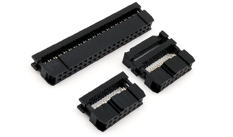
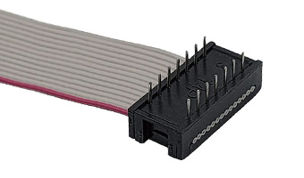
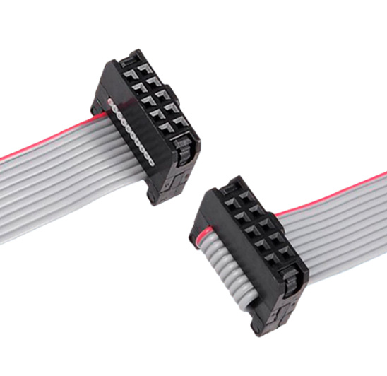
Para configuraciones multiconductoras repetidas, el Conjunto de cable plano IDC profesional de 2.54MM Utiliza cable plano de cobre estañado UL2651 de 28 AWG con paso de conductor de 1,27 mm, conectores IDC de 2,54 mm y configuraciones personalizables de 6 a 64 pines. Su carcasa de PBT negro cuenta con una estructura a prueba de fallos. El rango de temperatura de funcionamiento especificado es de -20 °C a +80 °C, y el producto cumple con la normativa RoHS.
El orden fijo de los conductores permite una asignación de pines repetible, pero la penetración de los contactos IDC y la orientación del conector aún requieren inspección. El cable plano también necesita una verificación de enrutamiento para evitar que se doble bruscamente a la salida del conector.
Mazos de cables de alimentación
Los circuitos de potencia requieren una tensión y una conexión a tierra correctas, especificaciones adecuadas para los cables y terminales, una sujeción segura, un aislamiento intacto y un ajuste correcto de los conectores. Las pruebas deben reflejar las condiciones de carga y funcionamiento aprobadas, pero no se debe asignar un límite de corriente general basándose únicamente en el calibre del cable.
Un arnés de alimentación puede pasar la prueba de continuidad a pesar de tener hilos dañados o un engaste débil. El aislamiento cortado, los hilos expuestos, la deformación de los terminales o los daños en la carcasa deben solucionarse antes de la aprobación.
Mazos de cables con conectores mixtos y ramificaciones múltiples
Un diseño con múltiples ramificaciones aumenta los riesgos de localización e identificación. Cada ramificación requiere el conector, la etiqueta, la longitud, la orientación y el diagrama de pines correctos. Las dimensiones de las ramificaciones deben medirse a partir de puntos de referencia definidos en el dibujo.
Las comprobaciones instaladas deben confirmar que ninguna rama cruza un componente móvil, bloquea otro conector o requiere fuerza para acoplarse. Las carcasas similares necesitan etiquetas y lógica de comprobación que indiquen una colocación incorrecta. El registro debe identificar cada rama en lugar de informar un resultado general para todo el mazo de cables.
¿Qué pruebas justifican la autorización para la producción en masa?
Una muestra exitosa constituye una evidencia útil, pero la aprobación también debe establecer cómo se repetirá el mismo resultado. El paquete de liberación debe vincular el diseño, el método de prueba, la referencia física y el registro de inspección.
El dibujo, el programa de pruebas y la muestra aprobada deben coincidir.
El plano debe definir los modelos de conectores y terminales, las especificaciones de los cables, la asignación de pines, la polaridad, las dimensiones finales, la posición de las derivaciones, las etiquetas y las tolerancias pertinentes. El programa de pruebas debe hacer referencia a la misma revisión y orientación de los pines.
La muestra aprobada debe llevar una referencia identificable. Puede aclarar la mano de obra y el trazado, pero no puede reemplazar los requisitos medibles. Antes de que comiencen las pruebas, los compradores también deben confirmar la Especificaciones de arnés de cables personalizado que definen la función del cable, la orientación del terminal, el color del cable, la longitud final, el etiquetado y los detalles de aprobación de la muestra. Cualquier cambio de material, terminal, conector o dimensión debe dar lugar a una revisión de las pruebas necesarias.
La revisión de la versión debe confirmar que producción, control de calidad y el comprador aprueban la misma configuración. Esto reduce el riesgo de que una muestra correcta sea seguida por un lote fabricado a partir de un plano o lista de materiales obsoletos.
Los registros de inspección deben permitir rastrear las fallas.
Un registro útil incluye más que una simple aprobación final. Identifica la revisión del plano, el accesorio, los elementos de prueba, los criterios de aceptación, la fecha, el lote y el resultado. Los hallazgos mecánicos y de ajuste deben registrarse por separado de los resultados eléctricos.
Los circuitos abiertos, los pines cruzados, las conexiones débiles, la desconexión de terminales, la interferencia del pestillo y la longitud incorrecta requieren diferentes medidas correctivas. Una etiqueta de defecto genérica ralentiza el análisis.
Los registros de inspección facilitan la trazabilidad al vincular las fallas con el material, la etapa del proceso, la configuración del equipo y el lote de producción correspondientes. Las verificaciones del producto terminado deben ir acompañadas de registros para poder rastrear los problemas y optimizar los procesos.
De una muestra única a un conjunto de mazo de cables repetible
Las pruebas de cableado no consisten en realizar la mayor cantidad de comprobaciones. Cada prueba debe responder a un riesgo definido. La continuidad y la identificación de los pines confirman la identidad eléctrica. La fuerza de tracción y la retención de los terminales confirman la seguridad mecánica. El ajuste durante la instalación confirma que el arnés completo se puede acoplar, enrutar y permanecer accesible.
La producción en masa solo debe comenzar cuando el plano, la muestra, el programa de pruebas y el método de inspección describan el mismo producto. ¿Tiene listo el diagrama de pines, la especificación de terminales y cables, el esquema de equipos o una muestra actual? Comparta los requisitos del proyecto con LeoCable. Revisar las comprobaciones eléctricas, los puntos de sujeción y el ajuste de la instalación antes de la aprobación de la producción.
Preguntas frecuentes
P: ¿Es suficiente una prueba de continuidad para aprobar un mazo de cables?
R: No. La continuidad confirma la existencia de una ruta eléctrica, pero por sí sola no garantiza la correcta asignación de pines, la polaridad, la retención de terminales, el cierre del conector, la longitud del cable ni el ajuste de la instalación. Estos puntos requieren verificaciones independientes según el plano y la aplicación aprobados.
P: ¿Cuál es el requisito de fuerza de tracción para un conjunto de terminales engarzados?
A: El requisito debe derivarse del terminal seleccionado, el calibre del cable, la construcción del conductor, la especificación de engaste y el plano del proyecto. No se debe aplicar un único valor a todas las combinaciones de terminal y cable. También se debe definir el método y el punto de aplicación de la fuerza.
P: ¿Debe probarse un mazo de cables dentro del equipo final?
A: Las pruebas en instalación son importantes cuando el proyecto tiene espacios reducidos, enrutamiento fijo, puntos de ramificación, conectores con bloqueo, curvas pronunciadas o acceso limitado para el servicio. Las pruebas en banco no permiten detectar completamente la interferencia entre conectores, cables atrapados, tensión continua en los terminales o problemas de enrutamiento relacionados con la carcasa.