

Table of Contents
Related news
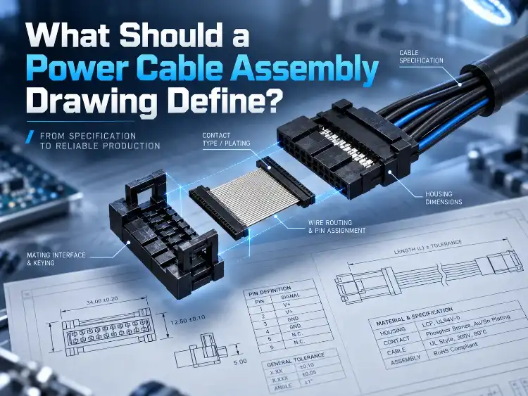
IDC Socket Pitch vs Ribbon Cable Conductor Pitch: How to Match Them
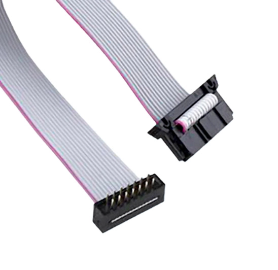
The IDC socket pitch and the ribbon cable conductor pitch are two different dimensions. Before you order, verify that the contact grid of the socket matches the cable conductor pitch specified for the cable. Also check the mating header, pin numbering and the orientation of the finished assembly. A single number such as “1.27 mm” does not establish compatibility.
When you replace a legacy assembly or send drawings to a new supplier for manufacture, a photo can look right while the contact layout or termination requirement is different. Buying safely starts with a dimensioned interface drawing and an approved pin map for the socket.
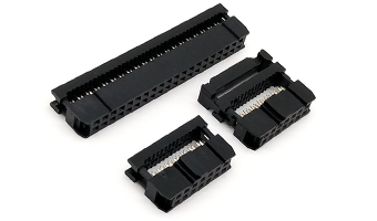
The IDC ribbon cable assemblies from LUONYX can serve as a starting point for discussing complete connections. The LUONYX IDC socket range covers several contact grids, and each grid should be specified in full.
Why Are Socket Pitch and Cable Conductor Pitch Different?
An IDC connection uses insulation-displacement contacts on the socket that pierce the cable insulation. The socket must have matching termination geometry for the cable. Measuring the mating envelope is a separate check from measuring pitch.
Specify the Full Contact Grid
IDC socket pitch is defined by two dimensions on the product drawing. Specify both values in the purchasing specification.
LUONYX IDC sockets are available in the following combinations. The first number is the contact pitch; the second is the row spacing. For example, 1.27 × 2.54 mm means 1.27 mm pitch with 2.54 mm row spacing, mating with 0.635 mm ribbon cable.
– 1.27 × 1.27 mm socket grid: 0.635 mm cable conductor pitch.
– 1.27 × 2.54 mm socket grid: 0.635 mm cable conductor pitch.
– 2.54 × 2.54 mm socket grid: 1.27 mm cable conductor pitch.
These pairings identify the listed product families. Always verify a specific part number with the supplier before ordering.
Do Not Apply a Half-Pitch Shortcut Blindly
Both 1.27 mm grid families (1.27 × 1.27 mm and 1.27 × 2.54 mm) use 0.635 mm cable, but the second grid dimension differs, and that changes the mating envelope. Never order “1.27 mm IDC” on its own – the supplier cannot tell which of the two families you mean.
The 2.54 × 2.54 mm socket is listed with a 1.27 mm cable conductor pitch. Do not describe that cable as 2.54 mm ribbon; list the socket grid and the cable conductor pitch as two separate fields. For the board-level trade-offs between the 1.27 mm, 2.0 mm and 2.54 mm grids, see which IDC pitch fits your PCB layout.
What Else Must Match at the Mating Interface?
The socket must seat in the mating header and preserve the required electrical relationships. Do not select on housing similarity alone. Check the actual parts.
Verify the Header and Mating Envelope
Identify the mating header by part number and revision where available. Compare contact count, grid, polarization features, housing clearance and the height available above the board. Include any latch or strain-relief arrangement in the envelope review.
Check both fit and access. An assembly may fit inside an enclosure while leaving too little room for an installer’s hand to engage a latch or to withdraw a socket with its attached cable. LUONYX develops the cable assembly and completes final assembly in-house. The IDC sockets are supplied by our affiliated IDC socket manufacturer. Use that capability to assess features such as cable exit direction and surrounding space, and to confirm which of the selected features are included in the proposed configuration.
Establish Pin 1 Without Guesswork
Draw the socket from the view labeled for the mating face. Mark Pin 1 on that view, mark the cable’s conductor-one convention, and show the connector orientation at both ends. An unlabeled front view can look like the reverse of what was intended when seen from the back.
A colored edge conductor is useful once a color convention has been defined, but it does not by itself prove that an assembly is correctly wired. Keep a separate, explicit pin-to-pin netlist as the electrical reference – particularly when replacing a cable whose history is unknown.
How Should Buyers Confirm the Cable Specification?
Selecting a ribbon cable conductor pitch also means selecting a suitable socket. In addition, the conductor size and cable insulation must be checked, because the pitch alone does not fully define a cable.
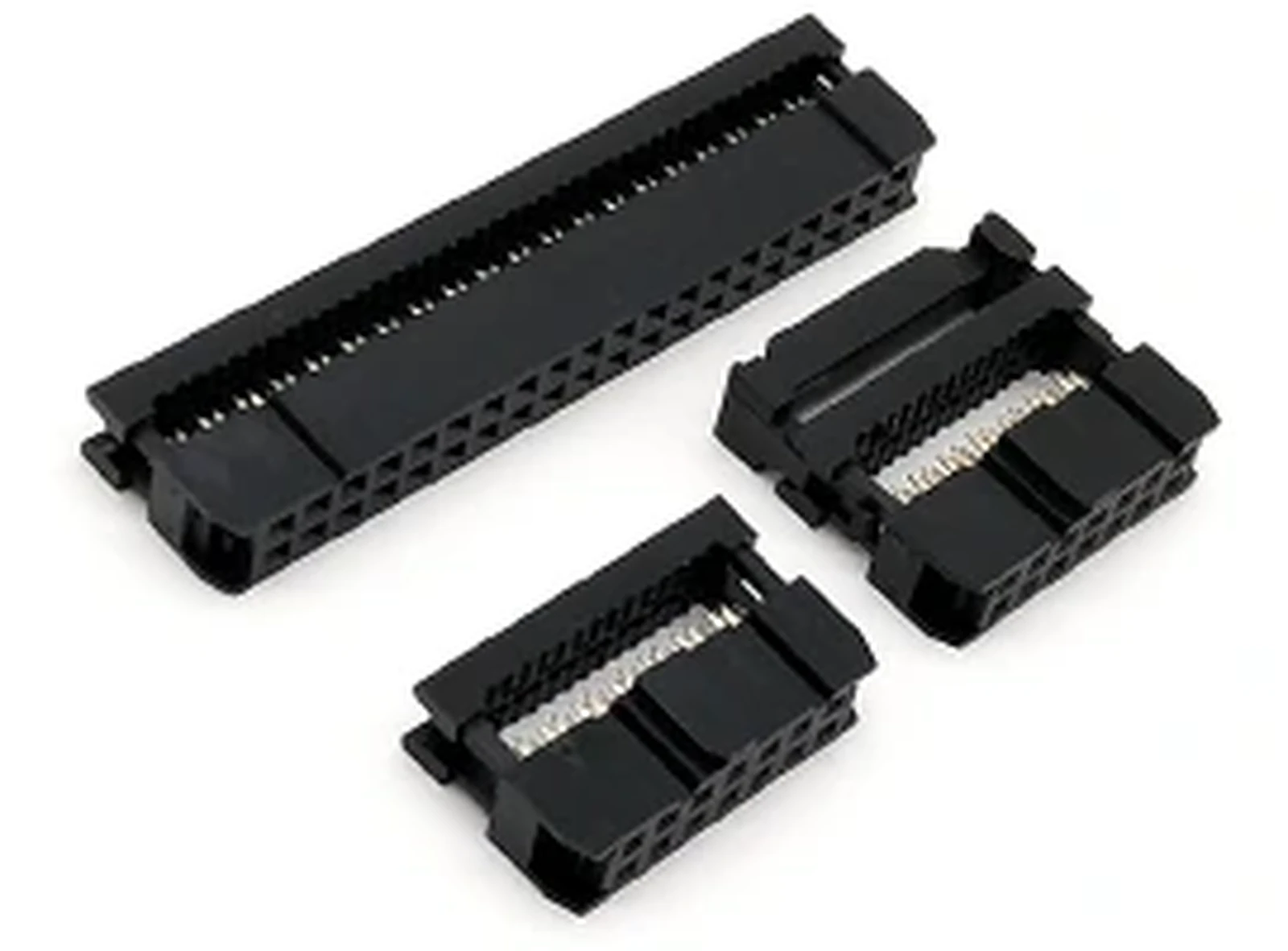
Tie the Cable to the Selected Socket Family
For each LUONYX socket family, link the cable conductor pitch to its part number using the pairing table above, and keep the full grid designation for the two 1.27 mm families even though both take 0.635 mm cable. Finished options are listed under IDC flat cables for these grids.
Confirm the permitted conductor construction, wire size, insulation dimensions and termination method for the specific socket with the supplier, and state any electrical or environmental ratings your application requires so that they can be checked separately.
Define Length and Routing Clearly
Indicate the finished length of the assembly between two reference points, and state whether the dimension includes the body of the connector or stops at the end of the cable. Indicate any folds, branches or constraints on how the cabling will be routed during installation.
What Should the Supplier Approve and Test?
Put the dimensions and electrical data in one package that Purchasing, Production and Inspection can all use as the single correct reference, without relying on verbal descriptions.
Approve One Complete Assembly Definition
Before production, resolve these items:
- Socket part, complete contact grid, and mating header.
- Cable conductor pitch and approved cable specification.
- Contact count, Pin 1 views, and pin-to-pin netlist.
- Length references, exit direction, and routing details.
- Drawing revision, inspection requirements, and identification.
For OEM and ODM work, we develop custom assemblies with you. For reproducing an existing assembly, provide the approved drawings or a sample for review; in either case the agreed specification must state clearly what is to remain unchanged and what will change.
Keep Full Testing Tied to the Approved Netlist
Every finished product is 100% electrically tested before warehousing – wiring definition, continuity, insulation resistance, conductor resistance and withstand voltage (hipot) – against the approved parameters. Ask for the test program and its acceptance records, and confirm that the program references the approved pin map and covers the relevant continuity and wiring-definition checks.
Electrical testing and mechanical verification have different objectives. A cable can pass a continuity test against an incorrect netlist, and a correctly wired assembly can still have the wrong mating envelope. Include a representative mating and installation check in the verification approval.
When a socket or cable substitution is proposed, review the affected drawings and repeat the relevant approvals before release.
Our Inspection Process
Quality is part of the specification. Our plant operates under ISO 9001, and our inspection system runs checks: incoming quality control (IQC) on raw materials, 100% electrical testing of finished products before warehousing, and outgoing quality control (OQC) sampling before shipment.
- 100% electrical testing (cable tester, every finished product): wiring definition, continuity, insulation resistance, conductor resistance and withstand voltage (hipot, at the maximum rating for each cable type), all checked against the parameters required by the engineering drawing.
- First-article inspection: insertion and extraction force is verified by first-article approval for connector products.
- Dimensional, material and process checks are sampled by our own inspection. Saltspray, flex and microsection examination are not carried out in-house: the material and plating suppliers run them and issue a test report with every batch. Product dimensions, material and process are measured with tape measures, calipers, rulers and micrometers; precision connector parts are checked with a 2D vision system.
- Supplier test reports: where we do not test in-house, the supplier provides a test report with every batch.
Conclusion
Treat socket pitch and cable conductor pitch as two separate specifications, and confirm the pairings listed above against the approved reference. On an industrial control board, the socket pitch must match the header row spacing before the board is soldered, so an error surfaces late and costs a full rework. Inside a server chassis, the flat-cable run must clear neighboring boards and latch access as well as match the conductor pitch. For bulk orders, ask us to review the assembly against the mating drawing, netlist, cable route, quantities and acceptance criteria.
FAQs
Q1: What size ribbon cable does a 2.54 mm IDC socket use?
A1: A 2.54 × 2.54 mm IDC socket takes ribbon cable with a 1.27 mm conductor pitch. Check the socket drawing before ordering.
Q2: Are the two 1.27 mm socket grids interchangeable?
A2: No. The 1.27 × 1.27 mm and 1.27 × 2.54 mm grids both use 0.635 mm cable, but the row spacing and contact layout differ. Verify the mating header against the approved reference.
Q3: Are bulk cable assemblies tested individually?
A3: Yes. Every finished product is 100% electrically tested before warehousing. The specific test items and acceptance limits follow the approved test program for each assembly.