
Table of Contents
Related news
What Must a Custom COM I/O Cable Drawing Confirm?
A custom COM I/O cable drawing should confirm the cable pinout, connector orientation, shield termination and assembly requirements before sample production. Those details are tied to a drawing revision and an inspection plan, and the sample is approved against that same revision before the bulk order is released.
Start with the equipment interfaces rather than a familiar connector photograph. The equipment owner confirms what each connection must do, and that information goes into the drawing. A recognizable connector shape should never replace a written cable pinout.
Which connections must the custom COM I/O cable drawing define?
The drawing should name both cable ends and keep those names consistent across the drawing, quotation and test record. The responsible engineer confirms the required signals and the equipment connection requirements.
Is the cable straight-through or a crossover?
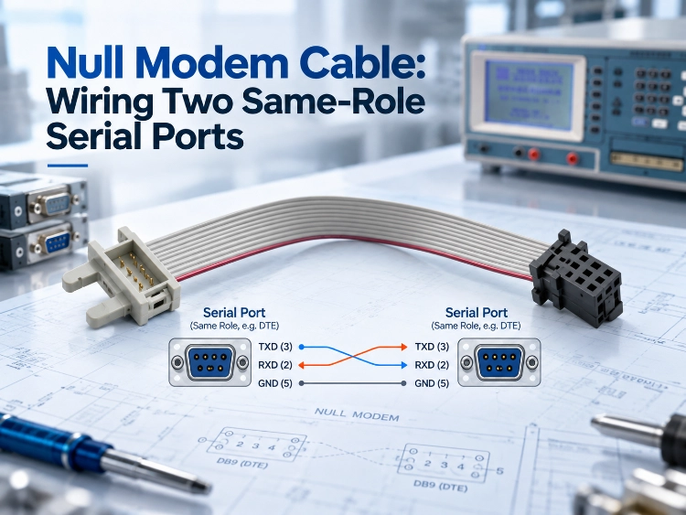
For COM I/O cables — typically RS-232 links with a DB9 (D-sub 9-pin) connector — the distinction between a straight-through and a crossover connection lies in the pin correspondence. A straight-through connection maps pin 1 to pin 1, pin 2 to pin 2, and so on. A crossover arrangement connects the transmit signal at one end to the receive signal at the other, where the equipment requires that arrangement.
If the required handshake uses RTS and CTS, include their corresponding crossover connections. The cable pinout is confirmed for the actual equipment rather than applying a generic 9-pin drawing without review. Unused positions and any other required connections are recorded explicitly.
The assembly style is discussed separately from the equipment-specific cable pinout, and the sample request includes the selected connector construction and the required electrical connections.
Connector viewing direction: mating face or termination side
Label each connector view as mating face or termination side, as appropriate. Our engineers confirm the pin-number references against the selected connector. The drawing carries the connector identifier and any orientation feature needed to read the view unambiguously.
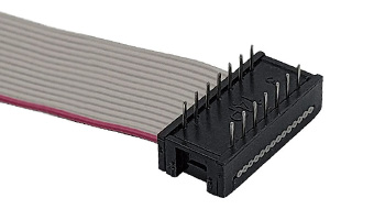
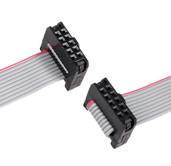
For a header-to-connector assembly, the drawing identifies the header reference, position-one marking and installed orientation. The equipment team reviews those details before the drawing is approved. Do not infer the electrical mapping solely from a stripe on a ribbon cable.
What should cable shielding instructions include?
Give cable shielding its own drawing notes. The system designer defines the required shield connection at each end, and our assembly team reviews how that connection will be made.
Where does the cable shielding terminate?
Specify whether the shield is connected or isolated at each identified end, together with the required termination construction. A note that says only “shielded cable” is not enough. A detail view is provided where the connection cannot be understood from the main assembly drawing.
Common shield faults include incomplete coverage, damage or missing sections. They also include improper grounding, a loose terminal connection and damage during cutting. These fault categories support the review of the proposed construction and inspection points, without assuming one grounding arrangement suits every system.
If a shield-performance result is required, ask the technical parties to agree on the test setup and acceptance criteria. The report request identifies the sample, termination configuration and relevant installation conditions. Any claimed result stays attached to that tested configuration.
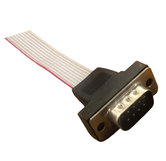
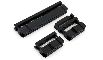
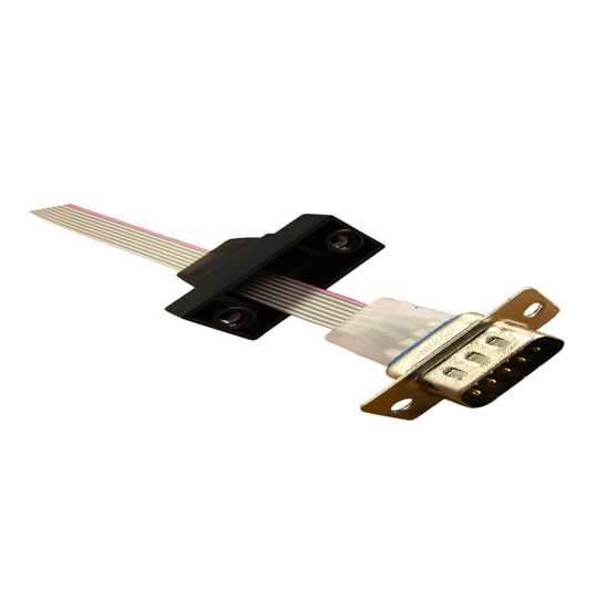
The first image shows the inner construction; the second shows the same cable with the snap-on hood fitted.
Which assembly details should reach production?
Assembly details carry the approved drawing into production. The sections below cover what must stay visible before assembly hides it, and what commonly fails at a terminal.
What must be inspected before it is hidden?
Ask us which termination details can be inspected before a cover, sleeve or molding conceals them. The appropriate production record or first-sample evidence supports that check, and the reviewer identifies what the evidence establishes and which electrical checks are still required.
The same applies to strain relief and cable exit orientation. The proposed routing space and assembly constraints are part of the technical discussion, and a representative fit check in the intended equipment is requested before accepting an installation-sensitive design.
Use the approved drawing to connect the design to the manufacturing instructions. We identify the process controls relevant to each termination type rather than applying a universal instruction to every cable.
What can go wrong at a terminal?
Possible causes of terminal detachment include insufficient crimping force, a misplaced crimp and a conductor cut too short. Damaged terminal clips or crimp structures, and forceful pulling during assembly, are other possible causes.
For crimped terminations, request confirmation of the applicable terminal and wire specification. Production equipment is set up and calibrated for each product before the run starts, and crimp position and force are set to the values on the approved drawing. The actual requirement for your selected terminal and conductor is agreed; no unsupported force value is inserted.
Work instructions that prevent a wrong pinout
Common causes of incorrect pin correspondence include failure to follow operating instructions, confusion between straight-through and crossover wiring, and unclear wiring markings. We show how the approved pinout will be represented in the work instructions and inspection record.
Production follows the drawing your engineers approved and the sample you signed off: connection rules, crimping parameters and shield-processing requirements are all fixed at that stage. For your custom COM I/O cable, the operations that apply to the selected construction are identified in the production plan.
How should the sample become a production reference?
Changes arising from the fit or electrical review are recorded in the next drawing revision, and the production order is released only against that revision.
What engineering support does LUONYX offer?
For custom cable assemblies, LUONYX follows an OEM/ODM process: we draft the drawing from your requirements for your confirmation, and where you supply the drawing we build to your revision. Either way, mass production follows the approved drawing revision and the sample you approve. The engineering team reviews the design for manufacturability and may recommend connector or cable construction changes. Initial samples are provided for customer testing and formal approval.
Review custom cable engineering support with your drawing, equipment interface details and expected quantity. During review, our engineers distinguish a manufacturing recommendation from a change requiring approval by your system engineer. Accepted changes stay in the drawing revision rather than only in correspondence.
Checks that belong in the acceptance plan
Test parameters are set against the drawing approved by your engineers and the sample you signed off before the run starts. At the start of the run, production submits a first article to our quality department, which verifies the workmanship, the electrical performance and the customer-specific requirements before volume production is released. Every finished product is then 100% electrically tested — wiring definition, continuity, insulation resistance, conductor resistance and withstand voltage (hipot) — against those parameters. Units that pass are visually inspected 100% for appearance before packing. Select the applicable checks and agree their methods, coverage and acceptance criteria for the assembly being purchased.
Insertion and extraction force is verified at first-article approval for connector products. Crimp pull-force testing is verified at first-article approval and re-checked by sampling during in-process patrol inspection (IPQC) and again at outbound inspection (OQC); minimum values follow IPC/WHMA-A-620 for the applicable wire size and product class, or the terminal manufacturer’s published specification where that is more demanding, with the governing value recorded on the drawing. Dimensional, material and process checks are sampled by our own inspection. Salt spray, flex and microsection examination are not carried out in-house: the material and plating suppliers run them and issue a test report with every batch. OQC re-checks the lot by sampling before release. Test and measuring equipment is calibrated on a regular schedule by a third-party calibration service, and calibration certificates are kept on file.
Each sample report identifies the drawing revision and sample reference, and mismatches are resolved before approval. Request a custom cable review with the cable pinout, connector views, shield notes and installation constraints so the quotation and sample discussion begin from the same technical brief.
Conclusion
Together, a manufacturability review and a controlled sample-approval process — such as the process LUONYX applies to custom COM I/O cables — give a practical route from your equipment requirements to an agreed production reference. Send the drawing revision with the pin map, connector views and shield notes; the quotation and the first article will then reference the same document.
FAQs
Q1: Can I approve the cable from a connector photograph?
A1: No. Straight-through and crossover COM connections differ only in their pin correspondence, which a photograph cannot show. An identified drawing with the pin map is requested, and the equipment owner confirms the required arrangement before sample approval.
Q2: Does a “shielded cable” note define the grounding?
A2: No. It describes the cable stock, not the build. Specify the shield connection at each end and the termination construction; grounding and terminal-connection faults are among the most common shield-related problems, so the system designer should approve the intended arrangement for the equipment.
Q3: When should mass production begin?