

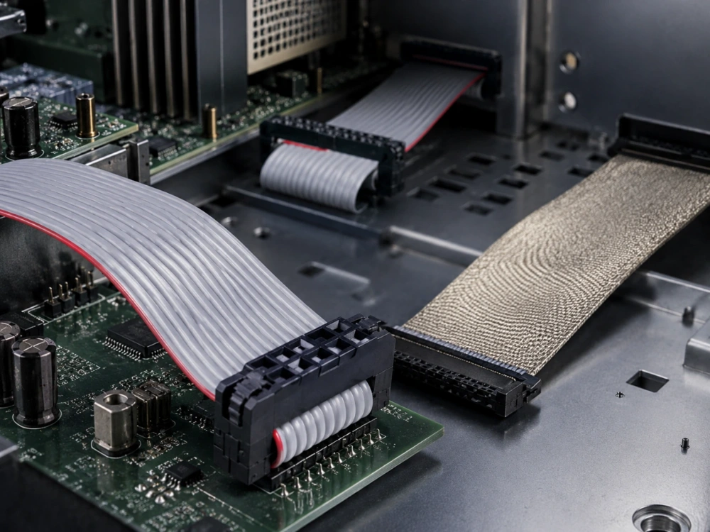
What Should a Power Cable Assembly Drawing Define?

A power cable assembly drawing should define the electrical path, connector system, mechanical protection, routing, and evidence that will be used to approve production. A connector part number or wire gauge alone is not enough. This controlled definition must tell the supplier what the assembly has to carry, where it connects, how it is protected, and how the approved result will be reproduced.
For buyers, this is where packaging, materials, current, voltage, cable lengths, and connector choices stop being separate conversations. This document turns them into one controlled product definition. It also answers a basic question that often appears during quotation: What is a cable assembly? In purchasing terms, it is a finished cable or wire group with controlled terminations, construction, testing, and release requirements.
What a Power Cable Assembly Drawing Must Define
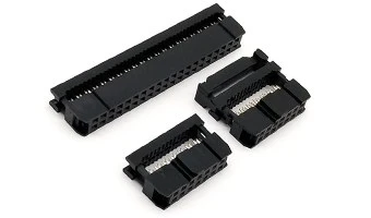
A useful drawing is a decision record. It should identify the revision, product function, electrical conditions, connector interface, cable construction, dimensions, routing, markings, sample status, and acceptance evidence. Every entry should belong to the selected products and application rather than a generic power cable category.
Electrical Load and Conductor Construction
Start with the conditions the assembly must survive. Voltage, current, duty cycle, ambient temperature, flexing, and environmental exposure determine how the conductor and insulation should be specified. Those inputs belong in the document rather than hiding behind a product name.
Conductor size and construction should then be tied to the approved cable specification. Strand count affects flexibility, while insulation material affects thermal and mechanical behavior. Termination method and any required electrical checks should also be defined. A documented SATA power cord assembly, for example, uses a 15-pin male connector, gold-plated contacts, UL1007 20AWG wires, and a PH2.0 termination. That combination is evidence for that product, not a universal value for every Power Assemblies design.
Power assemblies also need a clear voltage and current boundary when multiple conductors share one jacket or overmold. The released definition should map which conductor carries which circuit, how polarity is identified, and how the assembly will be tested after termination. When circuit traceability from the drawing to the finished sample is missing, the supplier cannot reliably reproduce it.
Connector Interface, Keying, and Retention
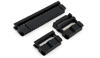
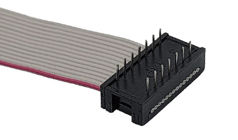
The connector interface should be defined from both sides of the connection. The interface record should include the mating connector, pitch or contact spacing, pin count, gender, keying, orientation, plating, and locking method. A connector that fits the header but cannot be keyed correctly creates a new failure mode after assembly.
Retention is separate from fit. The termination record should identify how the terminal or contact is secured in the housing, how the latch engages, and what prevents accidental disconnection. In a documented power cable assembly example, the connector, polarity, and termination details should remain traceable to the approved product definition.
Polarity and marking also belong on this part of the drawing. Color coding, labels, cavity numbers, and keying are production controls, not decoration. They help the assembler and inspector reach the same result. Required orientation and the inspection method for the connector interface also belong on the drawing.
Routing, Length, and Strain Relief
Finished length should follow the real route between connectors. A straight-line dimension is not enough when the cable must pass around a bracket, door, fan, or moving assembly. Measurement datum, finished length, tolerance, branch dimensions, and any service loop all belong in the length definition.
Strain relief should be defined where handling or vibration can load the termination. The strain-relief callout should define whether the assembly uses a molded strain relief, boot, clamp, heat-shrink transition, or another approved method. The same callout should identify the bend direction and minimum bend allowance that the sample must survive.
Routing protection has to remain visible in the approved definition. Abrasion points, sharp edges, cable ties, and service access can change the load on a connector after the product leaves the bench. When those conditions matter, include them in the drawing and the installed-fit check rather than relying on a note such as “route carefully.”
How to Turn the Drawing Into a Testable Supplier Package
A drawing becomes useful when the supplier can prove that the sample and production build match it. The package should connect the drawing revision to material records, process conditions, measurements, and test results. This is also the point where Cable Assemblies should stop being treated as a generic commodity.
Sample Approval and First-Article Evidence
Sample approval should freeze the revision that produced the sample. Cable, conductor, connector, terminal, plating, label, molding-material, and deviation details belong in that sample record. A first-article report should show the measured values against the drawing rather than only a pass or fail statement.
In the LEOCABLE ODM/OEM process, initial samples are provided for customer testing and formal approval before scalable production. The same approval model applies to a buyer using another supplier. The approved sample should be uniquely identified and retained so that a later change can be compared with the original condition.
The sample also needs a test boundary. A continuity-only check does not prove retention, insulation integrity, or connector fit. The package should state which checks were performed, where they were performed, and what evidence will accompany production.
What to Test Before Production
Electrical checks should start with the approved pin or circuit map. Continuity confirms that a path exists, while a programmed test can confirm that the path reaches the intended contact and that circuits which should remain isolated do not connect. Contact resistance, insulation resistance, and withstand-voltage checks should be included only when the product specification or application requires them.
Mechanical checks should prove the termination and assembly construction. Pull testing addresses the conductor-to-terminal joint; retention checks address whether the contact remains seated in the housing. Connector latch, strain relief, bend behavior, and installed fit answer different questions and should not be combined into one result.
Process records matter because a finished cable can pass once and still be difficult to reproduce. A documented COM I/O production-control example can include pin continuity, contact resistance, shielding effectiveness, insulation integrity, and tensile testing, with inspection logs supporting traceability. Apply that principle to the power cable drawing: every approved check needs a method, limit, record, and failure disposition.
How Overmolding Changes the Review
Overmold cable assemblies add a molded body around part of the cable and connector system. The added material can improve strain relief or sealing, but it also introduces tooling, material, shrinkage, gate, and dimensional variables. Mold and material condition must be defined in the approved drawing instead of treating the overmold as a decorative cover.
A separate review should compare the overmolded sample with the pre-mold assembly. Check that the connector is fully seated, the cable is not pinched, the strain relief engages the intended location, and the finished dimensions still fit the equipment. The overmold considerations are especially important when the assembly must also resist moisture, abrasion, or repeated movement.
Once the molded sample is approved, the tool, material, and process become part of the drawing revision. A material substitution or tool repair can change the result even when the electrical parts remain the same. The supplier should identify those changes before production and submit a new sample when the approved condition is affected.
Where Cable Assembly Standards Fit
Standards can provide a common baseline for construction, inspection, and documentation, but they do not replace the buyer’s drawing. Project-specific limits come from the drawing. The standard explains how a requirement may be evaluated or what workmanship context applies.
Workmanship and Component Standards
IPC/WHMA-A-620E describes materials, methods, tests, and acceptability criteria for cable, wire, and harness assemblies, including crimped, mechanically secured, and soldered interconnections. It can help a buyer review workmanship and inspection without becoming a product certification.
Wire and material recognition is another layer. UL Solutions states that Appliance Wiring Material is tested and certified to ANSI/UL 758 in the U.S.; that program concerns recognized wire and material constructions. A recognized wire does not automatically certify the finished power cable assembly, and the drawing must still identify the selected wire, connector, and process.
Connector test methods also need the correct scope. IEC 60512-1 provides a generic basis for connector tests and measurements, while the applicable detail specification sets the test, severity, and permissible limit. A standard number belongs in the drawing only when the buyer can identify the revision, clause, sample, and method that apply.
Project-Specific Limits and Evidence
Every measured characteristic needs a project limit. Define the unit, measurement point, sample or frequency, equipment, record, and response to failure. A resistance check is not complete without the method and limit; a pull check is not complete without the terminal-and-wire combination and force direction.
When the standard and drawing disagree, the more specific approved project requirement governs unless the customer contract says otherwise. A conflict between the drawing and product specification should be resolved by the buyer before production. The final drawing should contain one controlled value, not two numbers that leave the supplier to choose.
The acceptance sheet should mirror the drawing. Each line should identify what is checked, how it is checked, what result is accepted, and what happens when the result fails. This keeps the electrical, mechanical, visual, and process requirements in one reviewable structure.
Common Gaps That Cause Rework
Missing pin maps create incorrect assemblies even when continuity passes. An incomplete connector interface can produce parts that mate but do not lock. An unapproved overmold material can change dimensions or sealing behavior. A test plan without sample or frequency can leave production coverage undefined.
Other gaps appear when the drawing stops at the electrical parts. Length tolerances, wire routing, label placement, and packaging can change the installed result. Traceability also weakens when the record does not identify the drawing revision, material lot, or test station.
Rework prevention begins before quotation. The buyer should provide the current drawing, approved sample condition, and test limits together. If one input changes, the supplier should review whether the change affects the drawing, fixture, program, or approved sample.
What to Send With the RFQ
A supplier quote is only as useful as the requirements behind it. The RFQ should let the supplier quote the intended Cable Assemblies and the required evidence, not just a cable length and connector count. A clear RFQ should also explain where a standard product ends and a custom cable assembly scope begins.
Drawing and Material Inputs
Send the drawing revision, connector and terminal part numbers, conductor and insulation specification, wire colors, keying and polarity, finished length, routing constraints, environmental conditions, and any approved sample or reference product. Include the required labeling, packaging, and quantity where they affect the assembly.
For a multi-circuit power path, provide the pin or circuit map and identify the expected voltage and current for each. When shielding, grounding, flame performance, or a particular material is required, state the requirement and the supporting specification rather than relying on a generic product title.
For a custom harness or power cable, the specification process can overlap with the custom wire harness specification. Reuse the same discipline for the drawing, sample, and change control even when the product family differs.
Validation and Quantity Inputs
State the required sample quantity, first-article checks, test method, acceptance limits, and records that must accompany the shipment. Before quotation, identify any test equipment or fixture the supplier must provide. The quote should clearly say what is tested, what is not tested, and which limits still need customer confirmation.
Quantity affects tooling, molding, and production planning. Provide the expected order quantity, possible variants, target delivery, and any packaging or labeling requirements. When a post-first-article change is expected, define the revision path rather than allowing an informal substitute.
The final RFQ should include the commercial details without losing the technical boundary. The supplier needs enough information to quote accurately and to identify a requirement that cannot be supported. A complete request reduces the chance that a quotation is based on assumptions that the approved drawing later contradicts.
結論
A power cable assembly drawing should carry the electrical load, conductor construction, connector interface, retention, routing, overmold condition, test method, and acceptance record into one controlled revision. Review it with the supplier before sample approval, then verify that the first article and production plan use the same drawing and limits. The practical next step is to send the drawing, approved sample condition, test requirements, quantity, and delivery plan for a technical review. A professional ATX power switch cable assembly is one documented example of how a controlled cable assembly can be presented, while the actual power path and environment still determine the drawing.
よくある質問
Q1: What is a cable assembly?
A1: A cable assembly is a finished cable or wire group terminated with connectors or contacts and tested to an approved drawing or specification. It may include multiple conductors, terminals, labels, shielding, or overmolding.
Q2: What electrical information belongs on a power cable assembly drawing?
A2: Define the voltage and current conditions, conductor gauge and construction, connector rating, keying, polarity, insulation, and required electrical checks. Every value should match the selected product and application.
Q3: Why do overmold cable assemblies need a separate drawing review?
A3: Overmolding introduces tooling, material, shrinkage, strain-relief, and dimensional variables. The approved mold, material, and sample condition must match the drawing before production begins.