

Bảng nội dung
Tin tức liên quan
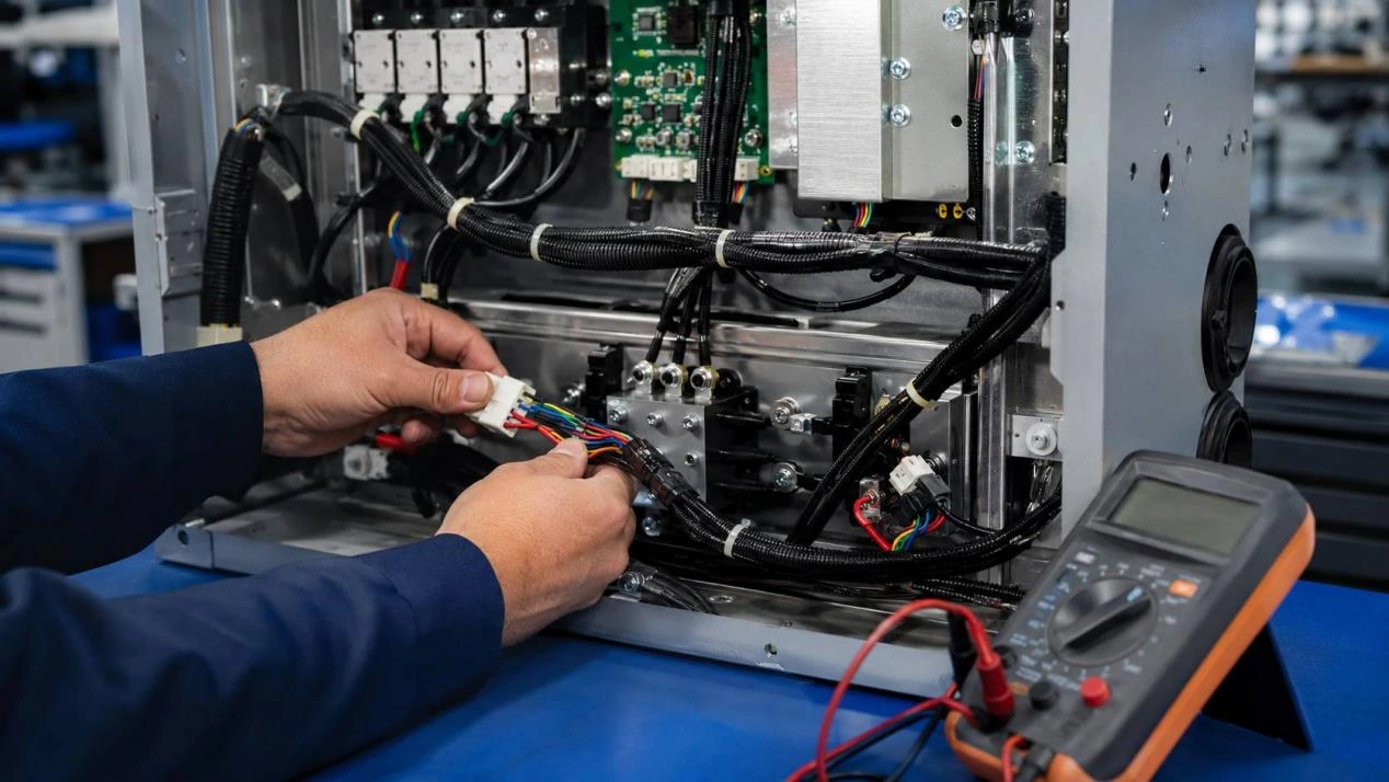
Ribbon Cable Problems: What Causes Failures Before Production?
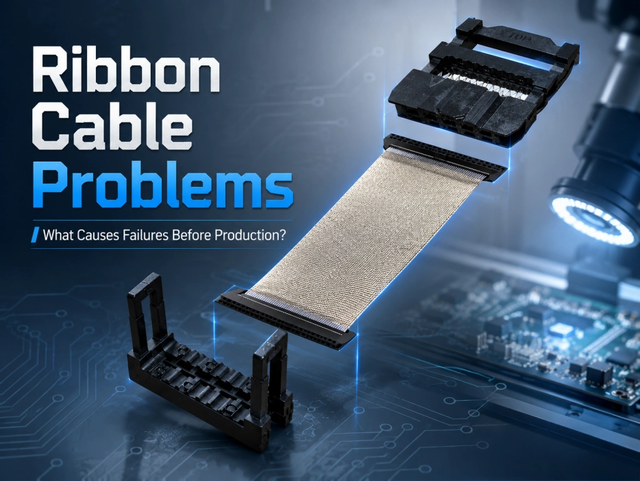
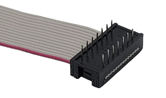
A ribbon cable can pass a quick bench check and still fail during pilot assembly. Common causes include incomplete IDC contact, wrong pin mapping, mismatched cable and connector pitch, weak retention, damaged insulation, poor shielding treatment, or a cable route that keeps pulling on the termination.
The useful question is not simply whether one sample works. Before production, buyers need to know whether the same electrical path, connector orientation, mechanical retention, and routing result can be repeated across a batch. A fault found at sample stage affects a few pieces. The same fault found after installation becomes a rework problem.
Why Can a Ribbon Cable Pass Testing and Still Fail Later?
A basic continuity check only proves that an electrical path exists at that moment. It does not prove that each conductor reaches the intended pin, that the IDC contact has fully reached the conductor, or that the connector will remain secure after routing.
Electrical continuity is only the first gate
With IDC termination, the contact must pierce the insulation and make stable contact with the conductor. Incomplete pressing can create intermittent behavior instead of a clean open circuit. Similar symptoms can come from a deformed contact, oxidation, or poor mating.
A ribbon cable tester should therefore run against a defined pin map, not only a simple continuity pass/fail result. It needs to distinguish the intended connection from crossed or unintended paths.
Straight-through and crossover wiring make this especially important. Straight-through wiring keeps the required pin correspondence. A crossover design changes selected signal positions. If production follows the wrong definition, the cable may be electrically complete but functionally wrong.
For a broader approval process, wire harness testing before mass production shows why pin mapping, retention, and installed fit should be treated as separate checks.
Installed fit can create a fault the bench never shows
The real enclosure adds bend points, brackets, covers, and nearby components. A cable that is slightly short may pull against a connector. A hard fold beside the termination can keep mechanical load on the contact area.
This is where a ribbon cable clamp, strain-relief feature, locking bar, or fixed routing point can matter. It does not improve signal quality by itself. It controls movement so the termination is not forced to carry the cable’s mechanical load.
Which Ribbon Cable Problems Should Be Traced First?
Troubleshooting is faster when each symptom is tied to likely process causes.
|
Failure symptom |
Likely area to check |
What to verify before production |
|
Intermittent signal |
IDC contact, mating contact |
Pressing quality and mating fit |
|
No signal or wrong function |
Pin map, wiring definition, orientation |
Point-to-point map against drawing |
|
Cable pulls away |
Retention, strain relief, handling |
Retention test and installed route |
|
Damaged insulation |
Cutting, pressing, handling |
Visual inspection after key steps |
|
Noise-related instability |
Shielding, grounding, routing |
Shield integrity and equipment test |
|
Excessive attenuation |
Cable length, contact quality, routing |
Electrical result in the real route |
Poor IDC contact often looks like an application problem
Intermittent faults may disappear when the cable is moved. Production control should check whether ribbon cable connectors are pressed evenly and whether the insulation-displacement contacts have reached the conductors correctly.
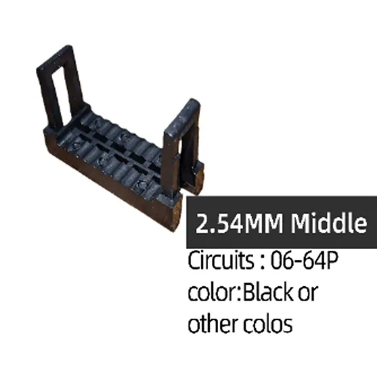
Acceptance criteria should match the chosen connector and cable specification. For example, LEOCABLE’s 2.54 mm IDC socket specification includes 20 mΩ contact resistance, 1000 MΩ minimum insulation resistance, 1 A AC/DC current rating, 250 V AC/DC voltage rating, and a -40°C to +105°C temperature range.
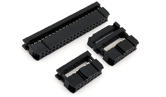
Teams using a standard industrial pitch can review the 2.54mm IDC Socket Connector when aligning housing structure, contact specification, pitch, and retention with the cable design.
Damage can begin before termination
An unsuitable cutting setting can score the insulation. Excessive pressure during assembly can damage the cable, while pulling during handling can transfer force into the connector.
A defect may remain hidden until the cable is bent inside the equipment. Visual inspection should therefore occur after cutting and again after termination, not only at final packing.
How Do Ribbon Cable Connector Types Affect Failure Risk?
Ribbon cable connector types are not interchangeable simply because they have the same pin count. Pitch, conductor spacing, mating structure, orientation, and retention all affect whether the assembly will work.
Match connector pitch to the actual wire pitch
For common IDC structures, housing pitch and conductor pitch are related but are not always the same number.
|
IDC structure |
Matching wire pitch |
|
1.27 × 1.27 mm |
0.635 mm |
|
1.27 × 2.54 mm |
0.635 mm |
|
2,0 mm |
1.0 mm |
|
2.54 × 2.54 mm |
1.27 mm |
This is an easy point to miss in an RFQ. Ordering by housing pitch and pin count alone can produce a connector that does not match the flat cable.
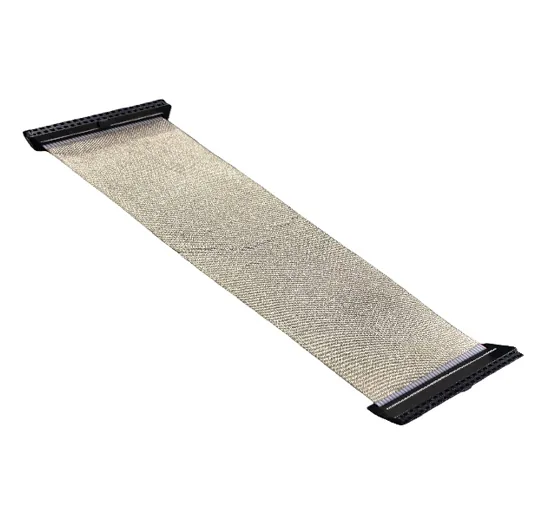
For applications that need several ribbon cable connector types, the Lắp ráp cáp linh hoạt IDC chuyên nghiệp supports 06-80P, interface pitches of 2.54 mm, 2.0 mm, 1.27 × 1.27 mm, and 1.27 × 2.54 mm, plus PH1.27 mm, PH1.0 mm, and PH0.635 mm wire spacing. Length can be customized, and the assembly is RoHS compliant.
Retention should match the equipment
A connector that works in a stationary fixture may not be enough for equipment exposed to vibration or repeated service. Fool-proof features, locking structures, mounting points, and strain relief can reduce wrong mating and gradual loosening.
A ribbon cable clamp or defined fixing point is useful when the route would otherwise pull directly on the connector. The key question is where the mechanical load goes after installation.
What Should a Pre-Production Ribbon Cable Test Plan Include?
A useful test plan separates electrical identity, contact quality, mechanical retention, physical condition, and installed behavior. One test cannot substitute for all five.
Start with pin mapping, not only continuity
A ribbon cable tester should confirm every required point against the approved pin map. If the design uses crossover wiring, the test program must represent that configuration.
Pin 1, connector viewing direction, cable stripe orientation, and mating direction should also be fixed in the drawing. An approved sample can clarify physical orientation, but it should not replace measurable requirements.
Add mechanical and visual checks
After electrical testing, inspect connector seating, cable insulation, strain relief, and locking features. Where retention matters, use a pull or tensile test appropriate to the selected termination and wire construction.
For shielded assemblies, inspect the shield for damage or missing coverage and confirm the required ground connection. Finished inspection can include:
- pin continuity and pin mapping;
- contact resistance where specified;
- insulation integrity;
- shielding integrity and grounding where applicable;
- retention or tensile testing;
- installed fit inside the target equipment;
- inspection records tied to the batch.
A ribbon cable tester is important, but it cannot show whether the cable will be pinched by a cover, loosen under routing stress, or be mixed with the wrong revision.
How Can Buyers Turn One Good Sample Into Stable Production?
A useful approved sample is a physical reference linked to the same drawing, material definition, test method, and revision that will be used for the batch.
Before release, fix the connector model, pin count, pitch, wire spacing, cable length, pin map, connector direction, Pin 1 identification, folding route, shielding requirement, retention method, and inspection criteria. Similar-looking versions should also have clear labeling and packing separation.
Incoming materials need control as well. Cable, contacts, shielding materials, and housings should match the approved specification. Cutting and pressing equipment should use controlled settings, and work instructions should clearly distinguish straight-through from crossover wiring.
LEOCABLE operates a vertically integrated manufacturing setup covering design and development through final assembly. Its product range includes connectors, IDC flat cable assemblies, and other internal equipment wiring, with OEM/ODM support for custom requirements. For buyers, the value is being able to align the connector, cable construction, sample, and production controls within one project.
If the design is moving from prototypes to repeat orders, manual or automated ribbon cable assembly can help determine when flexibility is still useful and when a more controlled production route makes sense.
When the drawing, expected volume, and installed route are ready, send your ribbon cable requirements to LEOCABLE to review connector format, cable specification, orientation, shielding, and production checks before batch release.
Phần kết luận
Ribbon cable failures before production usually trace back to incomplete IDC contact, wrong pin mapping, mismatched connector and cable pitch, weak retention, damaged insulation, shielding problems, or routing that loads the termination.
The practical way to reduce these risks is to approve more than continuity. Confirm wiring, connector orientation, conductor spacing, retention, insulation condition, and installed fit against the same drawing and approved sample.
Ribbon cable connectors should be selected as part of the complete assembly. Once the design is fixed, the test method and production records should make the approved result repeatable. That is what turns one working sample into a cable assembly ready for production.
Câu hỏi thường gặp
Q1: Can a ribbon cable pass a continuity test and still be defective?
A1: Yes. Continuity can confirm an electrical path, but it does not by itself prove correct pin mapping, stable IDC contact, connector retention, insulation condition, or installed fit.
Q2: What should a ribbon cable tester check before production?
A2: It should verify the required point-to-point connections against the approved pin map and identify open, crossed, or unintended connections. Mechanical retention, insulation, shielding, and installed fit still need separate checks.
Q3: How should buyers compare ribbon cable connector types?
A3: Compare pitch, wire spacing, pin count, mating direction, retention structure, contact specification, and the equipment route. The correct choice must match the PCB, cable construction, assembly process, and service conditions.