

Table of Contents
Related news

USB 2.0 Header Pinout Guide for Industrial PCs and Rear Panel USB Expansion
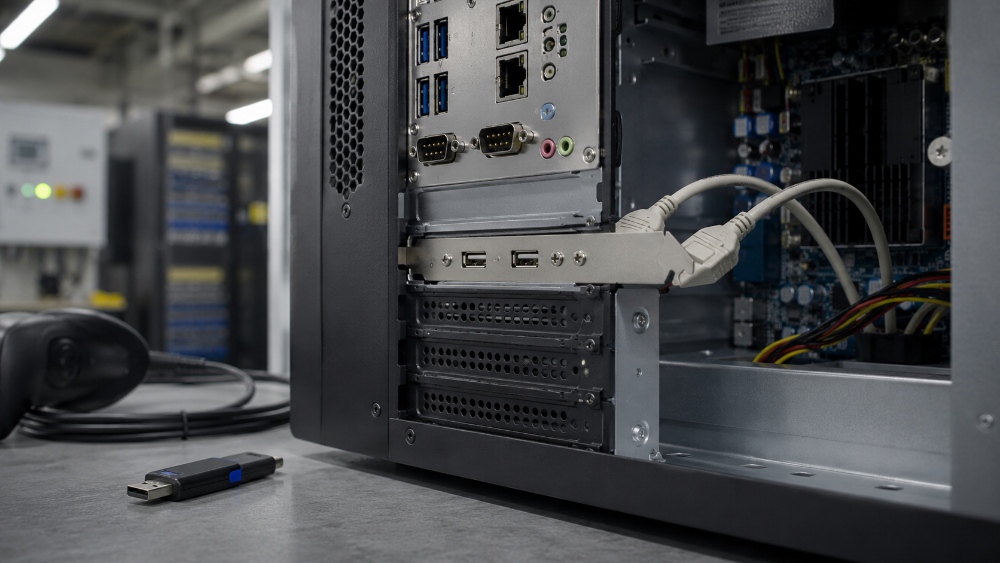
Industrial computers, servers, control panels, and embedded systems often need more than a front USB port. A stable rear USB interface can support maintenance tools, KVM access, barcode scanners, software dongles, and programming devices without exposing the system to loose front-panel wiring. The USB 2.0 header pinout is the starting point for that reliability, because one wrong signal line can stop a device from being recognized.
This guide explains the signal logic, internal wiring risks, and selection details behind rear panel USB expansion. It also shows how a suitable USB header cable can help system integrators build cleaner, more stable, and easier-to-service equipment.
What Is a USB 2.0 Header?
Before choosing a cable assembly, engineers need to know what the header is expected to carry. A USB 2.0 header pinout is not just a group of small pins on a board. It defines the power, data, and ground paths that allow the external USB port to work correctly.
Key signals: VCC, D-, D+, and GND
A typical USB 2.0 connection uses VCC for 5V power, D- and D+ for differential data transmission, and GND for the return path. These lines must remain in the correct order from the motherboard header to the USB Type-A port. If D+ and D- are crossed, the device may fail enumeration. If VCC and GND are reversed, the risk is far more serious.
USB 2.0 wiring also depends on clean contact between the board header, cable terminal, and external port. A loose connector, poor crimp, weak solder joint, or wrong pin orientation can cause intermittent recognition. In industrial devices, these small issues often appear as random failures, making them hard to diagnose during field service.
Why Rear-Mounted USB Ports Matter in Industrial Equipment
Rear-mounted USB ports are useful because they keep service access fixed, protected, and easy to manage. In a control cabinet, rack server, or industrial workstation, the technician may need a stable port that stays connected after the enclosure is closed.
Industrial PCs and control panels
Industrial PCs are often installed inside machines, cabinets, or narrow equipment bays. Front ports may be blocked, exposed to dust, or reserved for occasional use. A rear port supports fixed connections for programming tools, software keys, and device maintenance. For this type of application, an industrial PC USB cable should be stable mechanically and electrically, not just convenient.
Control panels have similar needs. A programmer, scanner, or service device may need fast access during commissioning. This rear-mounted approach helps keep the visible panel cleaner while still allowing reliable access from the system side.
Servers and maintenance ports
Servers and data center equipment often need USB access for KVM devices, local service, or management peripherals. A bracket-mounted dual-port design can add practical rear ports without changing the chassis layout. This is especially useful in repair centers, system integration projects, and custom builds where the original USB module is damaged or not enough for the final configuration.
Common Problems in Internal USB Connections
USB failures are not always caused by the USB device itself. Many problems come from internal routing, weak shielding, or mismatched connectors. Clean internal routing should reduce these risks before the equipment leaves production.
Pin mismatch and reversed connections
The first risk is simple but costly: the header and cable do not match. Some boards mark pin 1 clearly, while others use small silk-screen labels or rely on a manual. During assembly, technicians should confirm the direction of VCC, D-, D+, and GND before plugging in the cable.
Batch production needs extra care. When multiple similar connectors are placed near each other, a wrong connection can pass visual inspection but fail electrical testing. Clear labels, keyed connectors, and a controlled wiring definition help reduce errors. A system integrator should also verify whether the target board uses 2.0mm or 2.54mm pitch before placing an order.
EMI interference and unstable data transfer
Industrial systems often include motors, inverters, power supplies, and dense signal wiring. These parts can create electromagnetic interference that affects USB data lines. USB 2.0 uses differential signaling, but it still benefits from a well-shielded cable path, especially when the cable runs near noisy power sections.
An internal USB 2.0 cable should have shielding that protects the D+ and D- signal pair and limits external noise. Aluminum foil shielding and braided shielding can improve signal stability in cabinets, servers, and control systems. For long-term use, shielding also needs proper termination and physical protection, because damaged shielding may reduce interference resistance.
How to Choose a Board-Side USB 2.0 Cable for Rear Ports
A good choice starts with the board, the enclosure, and the use case. The cable should match the header pitch, fit the available space, and support the required data and power level.
Match the header pitch and connector format
Pin pitch is one of the most important selection points. A 2.0mm header and a 2.54mm header are not interchangeable. Even if a connector looks similar, forcing the wrong pitch can damage the header or create poor contact. For industrial projects, buyers should confirm the board drawing, sample board, or engineering file before mass production.
Connector orientation also matters. The cable should route naturally without sharp bending near the header. If the assembly needs to pass through a tight chassis path, a custom length can reduce stress and keep the interior cleaner.
Check data rate, power, and compatibility
USB 2.0 supports a maximum data rate of 480Mbps, which is suitable for many maintenance tools, barcode scanners, dongles, and standard peripherals. For power, many USB 2.0 devices use 5V/500mA as a common reference point. Compatibility with USB 1.1 and USB 1.0 devices can also matter in industrial environments, where older tools and legacy equipment may remain in service for years.
This does not mean every USB connection should stay with USB 2.0. High-bandwidth cameras or advanced storage devices may need newer standards. For stable maintenance access, control-panel peripherals, and rear service ports, USB 2.0 often remains practical and cost-effective.
Product Fit: Dual-Port USB 2.0 Header Cable for Industrial Use
After the pinout and installation requirements are clear, the cable assembly should support stable mounting, clear routing, and reliable data transfer. This is where the right bracket cable can reduce production and service issues.
Practical structure for rear expansion slots
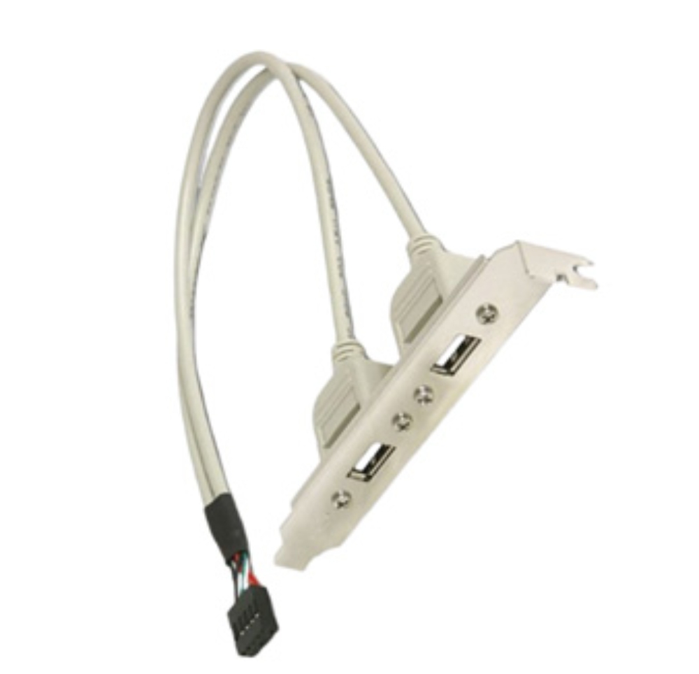
The Industrial-grade Internal USB 2.0 Header to Dual-Port Type-A Bracket Cable is designed for internal board-side USB extension in industrial PCs, servers, and high-performance desktop builds. It uses a 9-pin DIP male connector with gold-plated contacts for connection to the motherboard header, then extends to two USB 2.0 Type-A female ports mounted on a standard metal bracket.
The product supports custom cable length, black, beige, and other available colors, plus 2.0mm or 2.54mm pin pitch options. It supports up to 480Mbps data transfer and standard 5V/500mA power output. Its USB 2.0 compatibility, with backward support for USB 1.1 and USB 1.0 devices, makes it useful for both new builds and legacy maintenance environments.
Shielding, mounting, and service value
The cable uses individual pair shielding with aluminum foil and an overall braided shield to reduce EMI. This structure fits control panels, servers, industrial computers, and other equipment where signal lines may run near power or control wiring. The reinforced steel bracket helps prevent bending, while molded ports and strain relief improve durability during repeated insertion and service work.
For a system integrator, this type of internal USB 2.0 cable is not only a port extender. It can standardize rear service access, simplify spare-part replacement, and reduce the need for custom mechanical changes. Teams planning broader cable configurations can also review LEOCABLE for related internal wiring and connector options across equipment designs.
Installation Tips for System Integrators
Correct installation turns a suitable cable into a reliable connection. The process should be simple, but it should not be casual, especially when the same design will be repeated across many machines.
Confirm the header direction before assembly
Check the board manual, pin 1 mark, and header orientation before plugging in the cable. Do not rely only on the connector shape. In some compact systems, nearby headers may look similar, and a wrong match can create a failure that is difficult to see.
For prototype builds, test one sample before batch assembly. Confirm device recognition, stable data transfer, and power output with the intended peripheral. Once the sample passes, record the final USB 2.0 wiring direction, cable length, and bracket position for production.
Consider customization for cleaner equipment layout
Standard cable assemblies work for many chassis, but industrial equipment often needs controlled length, color, pitch, or terminal format. A cable that is too long can create clutter and raise the risk of bends or friction. A cable that is too short can pull against the header or bracket.
For projects that need different lengths, connector details, or production-ready cable assemblies, custom cable assembly support can help align the USB header, bracket position, and equipment layout before mass production.
Conclusion: Build Stable Rear USB Access from the Inside Out
Reliable rear USB access begins inside the equipment. The header layout must match the board, the connector pitch must fit, and the cable should provide enough shielding and mechanical support for the operating environment. A suitable industrial PC USB cable can reduce intermittent faults, improve service access, and make the internal layout easier to maintain.
For industrial computers, servers, control panels, or repair-center builds that need rear panel USB expansion, the right bracket cable can provide a clean and durable solution without heavy redesign. To discuss cable length, pin pitch, interface layout, or other project details, talk to our team about a custom USB cable assembly.
FAQ
Q:What is the main purpose of a USB 2.0 header cable in an industrial PC?
A:It connects the motherboard USB header to external USB ports, often on the rear panel. This gives technicians stable access for maintenance tools, KVM devices, barcode scanners, software dongles, and other low-to-medium bandwidth USB peripherals.
Q:Why does shielding matter for an internal USB cable?
A:Shielding helps reduce electromagnetic interference from motors, power supplies, inverters, and dense internal wiring. This is important in industrial cabinets and servers because interference can cause unstable device recognition or data errors.
Q:Should I choose a 2.0mm or 2.54mm USB header connector?
A:The correct choice depends on the board header. Always check the motherboard manual, PCB drawing, or sample board before ordering. A mismatched pitch can cause poor contact, difficult assembly, or connector damage.