

目次
関連ニュース
Advice On Selecting and Processing Connectors
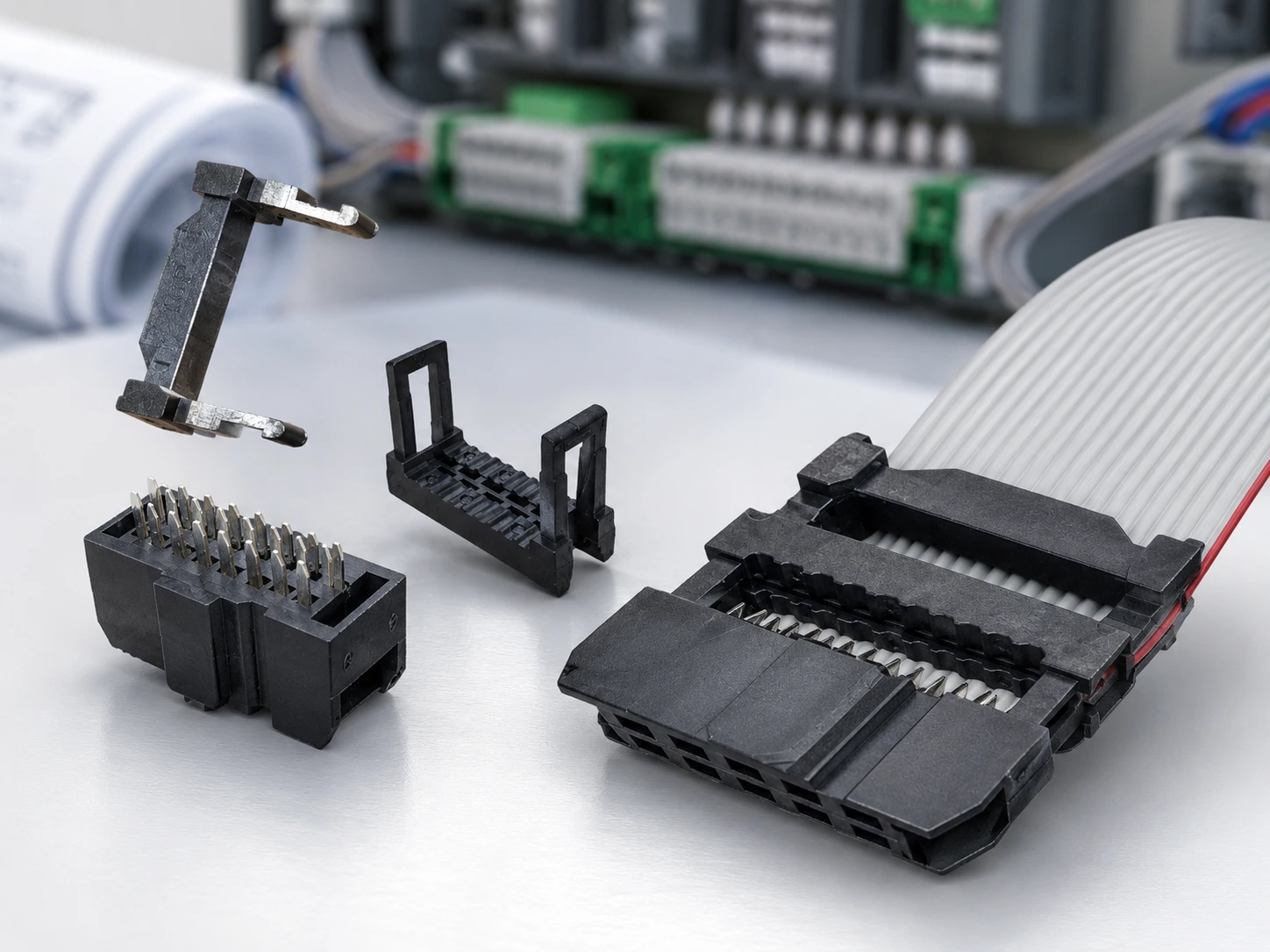
Connector selection looks simple only when the part is treated as a small accessory. In real equipment, electrical connectors decide how the PCB layout, cable route, terminal contact, production method, and final inspection fit together. A pitch mismatch can force a board redesign. A poor cable connector choice can slow assembly or create unstable contact after vibration, repeated handling, or dense internal routing.
A better decision starts with the connection role. Board-side connectors, cable-side connectors, and equipment-side interfaces solve different problems. PCB connectors are judged by pitch, pin count, mating height, and available space. Cable connectors must also match the wire or flat cable, the termination process, shielding needs, and the way the assembly will be inspected before shipment.
LEOCABLE’s connector and cable assembly work is strongest when the connector is selected together with the processing method. The practical question is not only which connector can mate with the board. It is whether the selected connector can be processed consistently, routed cleanly, and delivered as a stable cable assembly for the equipment where it will be used.
Start with the connection role before choosing electrical connectors
Board side, cable side, and equipment side create different risks
The first split is physical. A board-side connector protects PCB space and mating accuracy. A cable-side connector protects termination quality and routing. An equipment-side connector adds another layer: repeated installation, service access, shielding, panel space, or internal harness movement. Treating all of these as the same connector decision usually leads to a part that fits on paper but creates work later in production.
For example, PCB connectors for a compact control board may need a smaller pitch and a double-row arrangement. A cable connector for an internal flat cable needs a contact structure that can terminate several conductors in a repeatable process. An industrial interface may need stronger attention to terminal retention, cable jacket, shielding, or pin correspondence. The same electrical function can therefore require different connector families.
The connector choice also decides the cable process
A connector is not separated from the cable that enters it. If the cable is a multi-conductor flat cable, IDC processing may be the efficient route because insulation displacement contact can pierce the insulation and contact the conductor in one press. If the assembly uses discrete wires or a more flexible customized interface, crimped terminals may be more suitable because each wire can be terminated and positioned according to the required circuit.
This is why connector selection should be made before the cable assembly process is locked. The cable pitch, terminal interface, anti-interference requirement, and space limit all affect whether the final assembly is easy to produce or difficult to keep stable across batches.
How should PCB connectors match pitch, pin count, and space?
Pitch and pin count set the real layout boundary
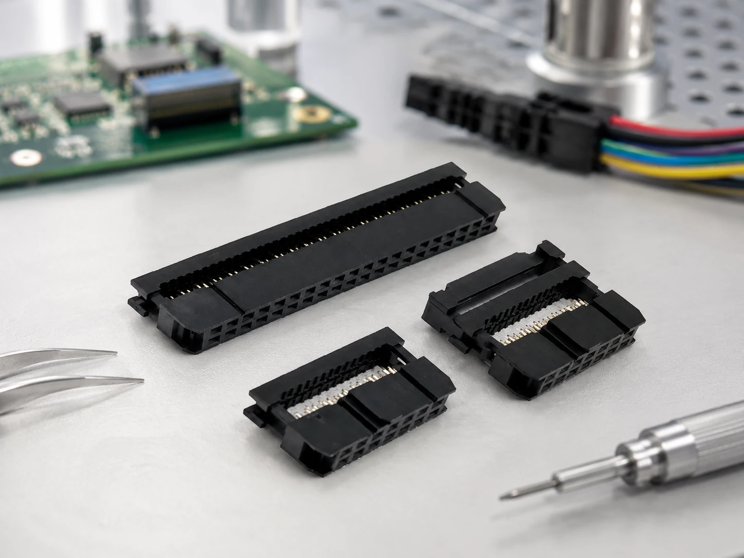
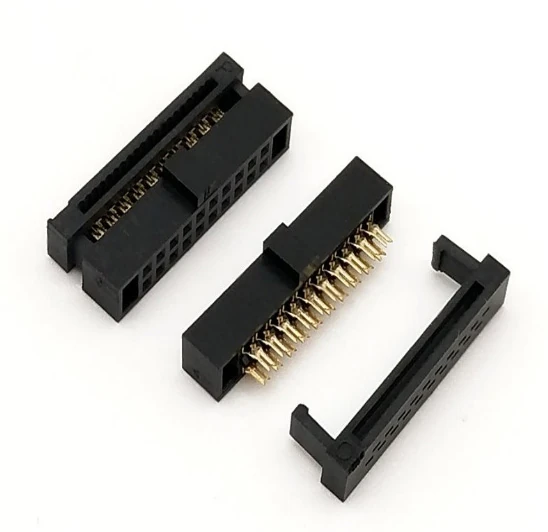
Pitch is not just a catalog number. It decides how close the pins sit on the PCB, how much routing space remains around the connector, and whether the mating cable can be assembled without stress. LEOCABLE’s IDC socket range includes pitch choices such as 1.27 x 1.27 mm, 1.27 x 2.54 mm, 2.0 mm, and 2.54 x 2.54 mm, giving engineers a way to match connector density with board space instead of forcing one pitch into every layout.
Pin count works the same way. More positions may be needed for signal groups, serial ports, control lines, or internal equipment wiring, but a higher pin count also increases the importance of alignment and pin correspondence. When a wire to board connector carries multiple signals, the connector must match both the circuit and the cable route, not only the board footprint.
IDC socket connectors fit dense flat-cable layouts
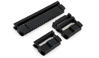
LEOCABLE’s IDC socket connectors use insulation displacement contact technology and are commonly assembled with multi-conductor flat cables. The structure supports one-press processing and double-row high-density layouts, which helps compact equipment keep internal wiring more orderly. In applications where a ribbon or flat cable connects to a PCB, this can reduce routing clutter and make production more repeatable.
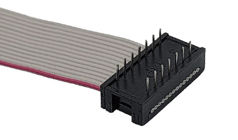
DIP plug and receptacle choices solve a different side of the same problem. They are useful when the mating interface, board arrangement, and service direction require a plug-style connector rather than an IDC socket alone. For PCB connectors, the best answer is often a matched set: the board-side interface, cable-side termination, pitch, and pin count are selected as one system.
Which processing method fits the connector and production volume?
IDC processing supports efficient flat-cable assembly
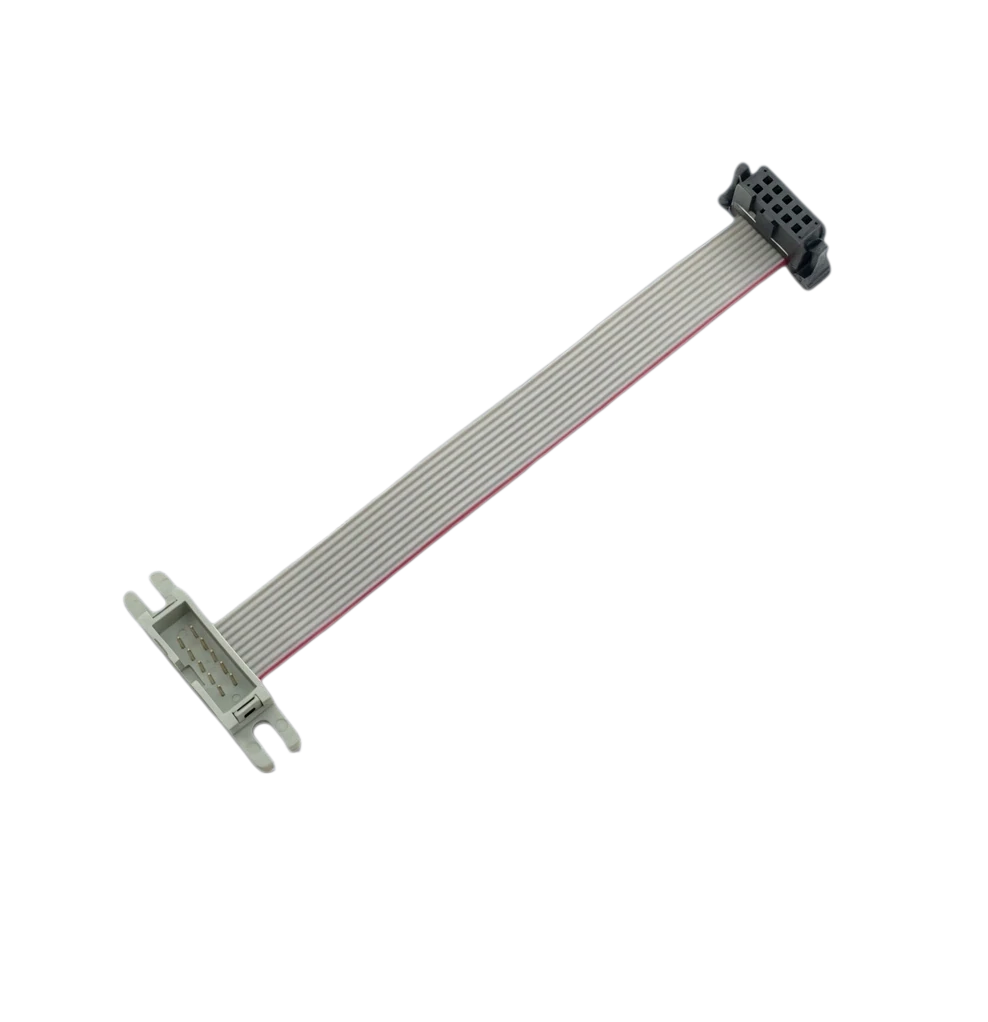
IDC processing is valuable when the cable is flat, the conductor spacing is predictable, and the production target favors repeatable batch assembly. With IDC sockets, the connector contacts the conductor through the insulation, so several conductors can be terminated at once. This is especially useful for internal equipment wiring where a flat cable needs to stay organized between a PCB and another module.
LEOCABLE’s IDC flat cable assemblies cover flat-cable products such as IDC socket flat cables and IDC-to-interface cable assemblies. In this type of work, the connector is chosen together with cable pitch, conductor count, and terminal direction, because those details decide whether the assembly can be pressed, inspected, packed, and installed consistently.
Crimped terminals fit flexible or customized interfaces
Crimped terminals are often better when the assembly uses separate wires, different branch lengths, or a connector interface that does not fit one-press IDC processing. They give more flexibility in wire routing and can support customized harness structures, but they also require attention to terminal pull strength, insertion position, and finished contact resistance.
Cable specification also matters. LEOCABLE’s COM I/O cable selection guidance separates common choices such as UL2651 28AWG gray flat cable and UL2464 shielded cable. The first fits many organized internal flat-cable layouts. The second becomes relevant when anti-interference performance is part of the equipment requirement. The right cable connector must therefore match the cable construction and the electrical environment at the same time.
What makes industrial connectors reliable in real equipment?
Environment decides cable, terminal, and housing requirements
Industrial connectors are judged after installation, not only during a desk review. Inside equipment, the cable may bend around panels, pass near motors or power sections, or share limited space with other harnesses. In those conditions, the connector housing, terminal material, pin alignment, cable type, and shielding choice all influence long-term stability.
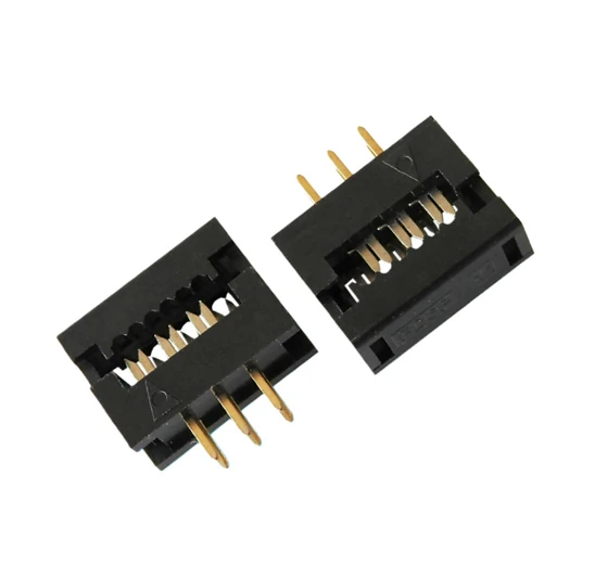
LEOCABLE’s 2.0mm DIP plug wire to board connector is one example of a connector designed around stable mating details. The product uses gold-plated terminal pins, PBT engineering plastic, a standard 2.0 mm pitch, a two-piece combination, and a triangular anti-misconnection mark. Its stated operating temperature range is from -40 C to 105 C, which makes the material and terminal choice part of the reliability discussion instead of a cosmetic detail.
Most production defects start as contact or correspondence problems
Common connector and cable assembly defects are usually practical: poor contact, shielding damage, insulation damage, wrong straight-through or crossover pin correspondence, terminal detachment, excessive resistance, or signal attenuation. These are not abstract quality terms. They appear when the selected connector, cable, processing route, and inspection method do not fit one another.
A stronger production route checks these risks before shipment. LEOCABLE’s quality-control logic includes raw material control, process control, and finished product inspection such as continuity, contact resistance, shielding effectiveness, insulation, and tensile testing. That matters because industrial connectors must arrive as working assemblies, not only as connector housings packed with terminals.
What details should be confirmed before connector production?
Confirm the mating interface before treating the connector as final
Before production, the connector decision should be reduced to concrete information: pitch, pin count, mating part, board position, cable type, wire gauge, shielding requirement, straight-through or crossover relationship, installation space, and expected production volume. If any of these details are missing, the chosen cable connector may still look correct but fail during assembly or final test.
For a PCB connector, the key details are pitch, pin count, orientation, and mating height. For a cable connector, the key details expand to cable construction, termination method, bend route, and inspection criteria. For a wire to board connector, both sides matter because the connector must satisfy the PCB layout and the cable-processing route at the same time.
Match the project to a real product range and production route
LEOCABLE was founded in 2013 and works as a cable and connector solutions provider with vertically integrated manufacturing from design and development to final assembly. That structure is useful when connector choice and processing method must be solved together: the conversation can move from connector pitch to cable specification, terminal process, inspection, and finished assembly without separating the problem into disconnected parts.
A practical next step is to compare the required interface with LEOCABLE’s connector range, IDC socket products, DIP plug products, and internal equipment wiring assemblies. If the project already has a drawing, sample, mating connector, or cable specification, the same information can be used to check pitch, pin count, cable route, and processing method before tooling or batch production begins. For a project that needs review, LEOCABLEに問い合わせる with the mating interface, cable specification, and application environment.
結論
Selecting connectors is not a separate purchasing step after the design is finished. It is part of the equipment connection system. Electrical connectors affect PCB space, cable routing, terminal processing, shielding, inspection, and long-term contact stability. A connector that only matches the drawing may still create production defects if the cable type, processing route, and use environment are not considered.
For LEOCABLE projects, the strongest connector choice is the one that can be produced as a stable assembly. IDC socket connectors fit many compact flat-cable and PCB layouts. DIP plug and wire to board connector options help when the mating interface and board arrangement require a plug-style solution. Industrial connectors need extra attention to contact, shielding, insulation, and terminal retention. Confirming pitch, pin count, mating part, cable specification, and application environment early makes the connector easier to process and easier to trust in finished equipment.
よくある質問
Q1: What information is needed before selecting electrical connectors?
A1: The useful starting information includes pitch, pin count, mating part, board position, cable type, wire gauge, shielding requirement, terminal method, installation space, and production volume. These details show whether the connector should be an IDC socket, DIP plug, crimped terminal solution, or another wire-to-board interface.
Q2: When are IDC socket connectors better for cable assemblies?
A2: IDC socket connectors are a strong option when a multi-conductor flat cable needs organized, repeatable termination. Their insulation displacement contact structure supports one-press processing, which is useful for compact PCB wiring and internal equipment cable assemblies.
Q3: Why should connector selection include processing requirements?
A3: Processing requirements decide whether the connector can be assembled consistently. A connector may match the PCB footprint, but the finished cable assembly can still fail if the cable pitch, terminal method, shielding, pin correspondence, or inspection standard does not match the production route. LEOCABLE reviews connector and cable assembly details together so the selected part can become a stable finished assembly.