

جدول المحتويات
أخبار ذات صلة
What Should Cable Assembly Testing Prove Before Bulk Production?
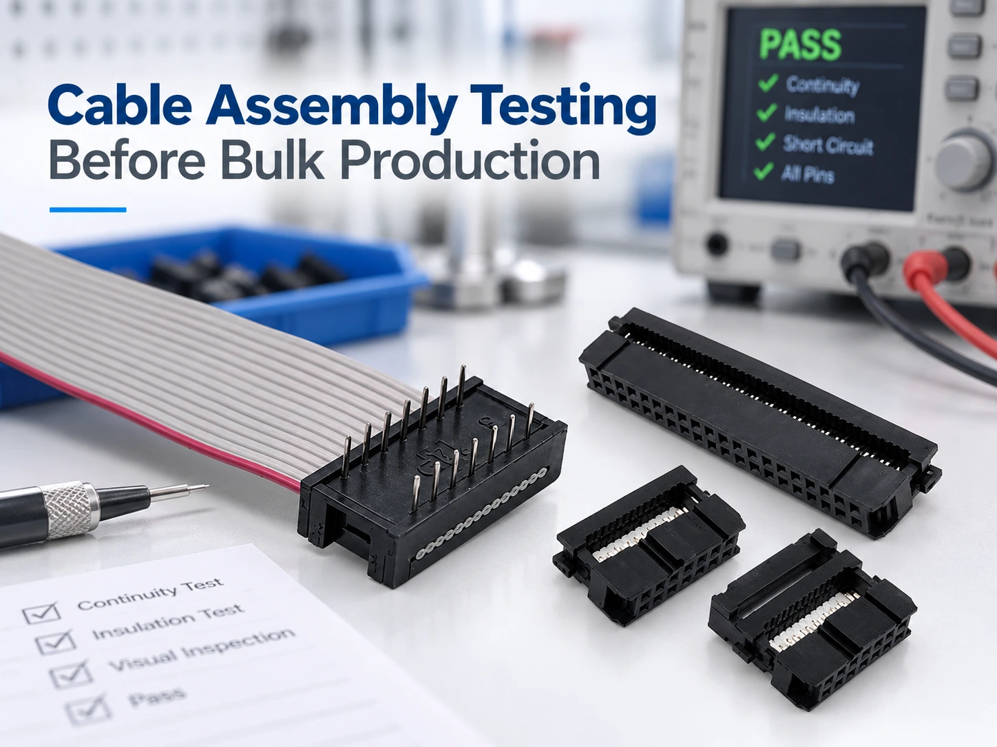
Cable assembly testing before bulk production should prove more than whether one sample powers on. The buyer needs a defined drawing revision, application risk, test method, fixture, acceptance limit, sample approval, and release record that will govern the batch.
Treat cable assembly testing before bulk production as a controlled chain: approved drawing, test procedure, qualified cable assembly tester and fixture, measurable limits, approved sample, and documented release rule. If one link is missing, a report can look complete while the production process remains undefined.
What the Test Plan Must Prove Before Bulk Production
A test plan should prove that the supplier can reproduce the required electrical, mechanical, dimensional, and visual characteristics. It must also define how a failed unit is identified, segregated, corrected, and retested.
The Drawing and Application Risk Define the Boundary
Start with the approved drawing, not a generic test list. It should define connectors, pin numbering, wire construction, length, orientation, labeling, shielding, and the revision used for inspection. Application risks such as vibration, repeated mating, and electrical load then set the test depth.
Risk determines coverage. A protected low-voltage control cable may need fewer checks than a safety circuit, a high-vibration harness, or a cable that must preserve signal integrity. Open circuits, crossed pins, shorts, weak retention, insulation damage, and shielding faults require different tests.
For the physical checks behind continuity, pull force, retention, and installed fit, see the related guide on continuity, pull force, and fit checks. This article focuses on the buyer-controlled test procedure, equipment, limits, sample approval, and release evidence.
A Passing Test Is Not Yet an Acceptance Rule
A result is acceptable only when the unit, method, limit, record, and failure disposition are defined. “Continuity passed” is incomplete unless the tester program, fixture, pin map, and isolation requirements are identified.
One measurement is not an acceptance rule. Every check should connect to a source-traceable limit and evidence. A 15 mΩ post-crimp limit, for example, belongs only to the specified terminal, wire, tool, and process condition.
Records must carry a revision identity. If the drawing changes, the pin map, fixture, program, and acceptance sheet should change with it; otherwise a batch can pass an obsolete test.
How to Build a Cable Testing Procedure for a Custom Assembly
Write the cable testing procedure before quotation. It should define the check, method, equipment, coverage, acceptance rule, record, and exception owner so two qualified operators reach the same decision.
Start With Failure Modes and Cable Construction
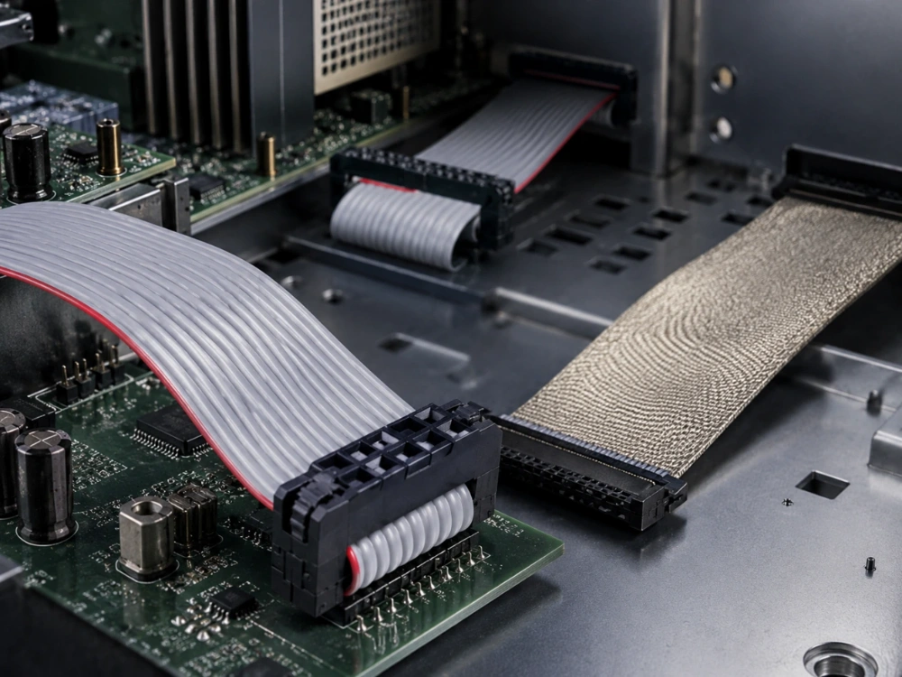
Start with the assembly architecture. IDC assemblies depend on conductor alignment, insulation displacement, latch engagement, and pitch compatibility. Crimped assemblies depend on strip length, terminal choice, crimp force, conductor placement, and pull strength.
Wire construction matters too. Strand count affects flexibility, insulation affects thermal and abrasion performance, shielding controls interference, and jacket thickness affects routing. Direct inspections and incoming-material controls should be assigned deliberately.
Incoming material control can check insulation thickness, contact resistance, and shielding effectiveness. Production control should calibrate crimping to the wire diameter, maintain cutting and crimping equipment, control straight-through or jumper rules, and qualify operators before work begins.
Choose Electrical, Mechanical, and Visual Checks
Electrical checks usually include continuity, pin mapping, isolation, and product-specific contact or insulation measurements. A programmed test confirms the intended path and detects shorts, opens, and incorrect connections; resistance and withstand-voltage limits must match the product specification.
Mechanical checks cover wire-to-terminal pull strength, contact retention, latch engagement, strain relief, bend performance, and repeated mating. A crimp pull test and a housing-retention check measure different failure modes and should not be combined.
The application environment also shapes the test plan. Shielding and grounding matter on interference-sensitive runs, while conductor size and insulation affect resistance and signal loss over distance. A basic continuity pass cannot prove those conditions.
Visual and dimensional inspection should verify conductor and insulation condition, terminal orientation, insertion depth, latch condition, polarity, labeling, length, and branch location. Packaging controls also matter when later handling could damage the assembly.
Coverage must follow the approved construction. An IDC or crimped joint can be right for one wire, volume, and service condition but wrong for another; see the IDC or crimp termination discussion. The procedure should verify the selected method.
Make 100% Testing the Production Baseline
For LEOCABLE cable assemblies, 100% testing is the production baseline: every unit is checked before release, including units built in bulk production, using the approved test method and acceptance criteria. Destructive, environmental, or periodic checks that cannot be applied to every unit may supplement that baseline through a documented sampling plan, but they do not replace the per-unit test.
Standards can guide coverage without making the project decision. NASA-STD-8739.4A requires continuity, dielectric withstanding voltage, and insulation-resistance checks within its high-reliability scope, but that standard does not set every commercial assembly limits.
Select and Qualify a Cable Assembly Tester
The tester is part of the acceptance system. A correct measurement range can still produce misleading results if the fixture applies the wrong load, the mating connector is worn, the program uses an old pin map, or the setup cannot be reproduced.
Fixture, Mating Connector, Calibration, and Program Control
The fixture should hold the assembly consistently, protect the connector, and use controlled mating connectors with wear criteria. Calibration records should link to the specific cable assembly tester and production period.
Program control should identify the assembly, drawing revision, pin map, continuity paths, isolation pairs, resistance limits, and sequence. Program changes should follow drawing review, and known-good and known-bad samples should verify failure detection after setup changes.
IDC families illustrate the point. A 1.27 × 1.27 mm assembly uses a 0.635 mm terminal contact pitch, while 2.0 mm and 2.54 mm families use different pitches. The fixture and program must match the connector family, cable pitch, circuits, and latch geometry.
Find Intermittent and Routing-Related Failures
A static continuity check can miss a terminal that opens only when the cable bends, a contact that moves after mating, or a shield that loses connection under vibration. The plan should state how the assembly is exercised and which circuits are monitored.
Repeated mating and bend testing are not the same as a first-article electrical check. Define cycle count, motion, inspection intervals, and final acceptance before testing, and record the fixture, setup, and sample condition.
Where Cable Testing Standards Fit and Where They Do Not
Standards give a common language for workmanship, test methods, material recognition, and acceptance criteria. They do not replace the customer drawing, application risk assessment, or supplier process specification.
Use Industry Standards as a Baseline, Not a Blanket Claim
IPC/WHMA-A-620E describes materials, methods, tests, and acceptance criteria for cable and wire harness assemblies. It can inform workmanship and inspection, but it does not set the electrical limit for a specific product.
High-reliability standards show how far requirements can extend. NASA-STD-8739.4A requires continuity, dielectric withstanding voltage, and insulation-resistance checks within its scope, not for every commercial assembly.
Material and connector standards answer different questions. UL 758 concerns recognized Appliance Wiring Material. IEC 60512-1 provides a generic basis for connector tests, while the detail specification sets the test, severity, and permissible limit.
This is where cable testing standards are often misused. A supplier may name a standard without identifying the revision, clause, sample, method, or limit. Trace each claimed requirement to the drawing, material specification, workmanship rule, or customer test plan.
Convert the Drawing and Product Specification Into Limits
A standard can define a method without defining the project’s pass value. The drawing and product specification should supply the target, tolerance, unit, measurement point, sample size, and frequency.
Write the acceptance sheet in production language. Each row should state the characteristic, method, equipment, sample or frequency, limit, record, and reaction to failure. Use the connector selection and processing guidance for upstream choices that determine process control.
Unknown limits are open engineering items. Do not let a supplier choose a convenient value or copy a number from an unrelated product; record who defined the limit and which revision made it effective.
Approve the Sample, Then Freeze Batch Release Evidence
Sample approval is a transition point. Before approval, the project is still proving the design; afterward, the supplier must reproduce the same result with controlled materials, processes, equipment, and records. That transition should be explicit.
What Sample Approval Should Lock
Freeze the drawing revision, bill of materials, approved sources, connector and terminal part numbers, wire construction, finish, shielding, and any deviations. Also fix the tester or station, fixture, mating connectors, calibration, program revision, and acceptance limits.
The LEOCABLE ODM/OEM process provides initial samples for customer testing and formal approval before scalable production. The same principle applies to any supplier: approval is useful only if the approved condition remains controlled.
What the Supplier Should Submit Before Bulk Production
The package should compare the proposed process with the approved sample. Include the drawing, bill of materials, process flow, test procedure, acceptance sheet, tester and fixture identification, calibration, program revision, first-article data, test results, and deviations.
For multiple variants, identify which records cover which version. Inspection records should show the unit or lot, date, station, measured result, limit, and disposition, and link back to the material lot or process condition when a failure occurs.
Finished-product inspection for COM I/O cables can include pin continuity, contact resistance, shielding effectiveness, insulation integrity, and tensile testing, with inspection logs used for traceability. Submit evidence for every controlled characteristic, not only the easiest electrical test.
How to Handle Failures, Rework, and Retest
Define failure handling before production. Quarantine the affected units, preserve the record, identify the failure mode, determine containment, and assign a disposition such as scrap, rework, approved use-as-is, or return to the supplier.
Retest scope should match the risk. A reterminated connection may need electrical, pull, and visual checks; a labeling correction may need only the affected inspection. Record the original failure, corrective action, retest result, and release authority.
A sample failure should trigger a review of the represented population, the process condition that produced it, and whether completed units share the risk. The response should be a controlled disposition, not only a replacement shipment.
A Supplier Brief for Cable Assembly Testing
Clarity gives the buyer leverage. A supplier who receives the drawing, application context, test expectations, acceptance rules, and evidence requirements can quote against the same definition and expose gaps before production.
Requirements to Send With the RFQ
Send the connector and terminal part numbers, cable construction and gauge, pin map, finished length, branch or orientation requirements, shielding and grounding, environmental conditions, labeling, packaging, target quantity, schedule, test categories, limits, and customer specifications.
Ask the supplier to identify equipment, fixtures, calibration, program control, 100% per-unit testing coverage, and shipment records. The quotation should state the approved 100% test coverage, any supplemental checks, and which limits require customer confirmation.
A documented example helps clarify the expected level of detail. Use the documented USB 3.0 A to B cable assembly as a reference when discussing connector, wire, test, and approval information with a supplier.
Evidence to Review Before the Release Meeting
Before release, review the final drawing, approved sample ID, test procedure, tester and fixture qualification, calibration, program revision, first-article results, and open deviations. Confirm that measured values link to the correct limit and tested unit or lot.
The release meeting should also cover capacity and response. Ask whether qualified stations can support the volume, what happens when a tester is unavailable, how failures are contained and retested, and which records ship with the lot.
Approve bulk production only when drawing, procedure, equipment, sample, limits, and records agree. If one element is missing, close the gap instead of assuming the first production run will reveal it.
خاتمة
Approve the chain, not a folder of passing values: drawing and risk boundary, cable testing procedure, qualified cable assembly tester and fixture, correct cable testing standards, approved sample, and controlled release records. Ask how every result will be produced, measured, recorded, and dispositioned when it fails. Then share the drawing, cable construction, checks, sample plan, and target quantity for a documented cable assembly review.
أسئلة متكررة
Q1: What is the difference between cable assembly testing and a cable testing procedure?
A1: Cable assembly testing is the measurement or inspection performed on the assembly. A cable testing procedure defines the unit, setup, method, limit, record, and failure disposition that make the result repeatable.
Q2: Does every cable assembly need 100% testing before bulk production?
A2: Yes. ليوكابل uses 100% testing for its cable assemblies, and every unit is checked against the approved test method, fixture, and acceptance limits through bulk production. Destructive or periodic checks may supplement that 100% unit test, but they do not replace it.
Q3: What should be approved before bulk production: the sample, the procedure, or both?
A3: Approve both. The sample shows that the assembly can meet the requirement; the procedure, tester, fixture, limits, and records show how the supplier will reproduce that result across the batch.