

Tabel isi
Berita terkait

Why Do Ribbon Cable Assemblies Fail in Industrial Equipment?
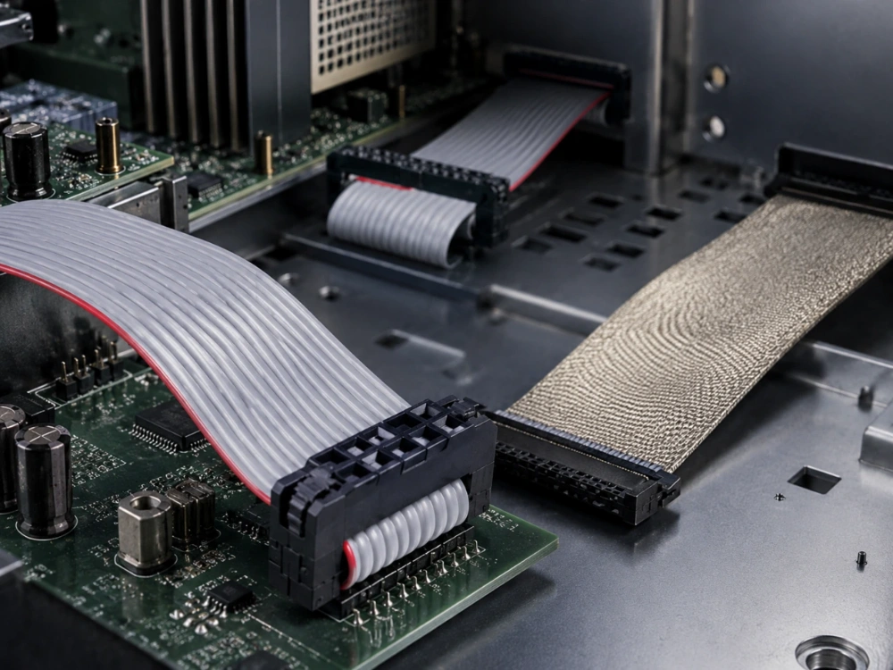
Ribbon cable assemblies usually fail because the connector, cable, pin map, termination process, and installed route do not work as one system. An assembly may pass a quick continuity check on a workbench yet develop intermittent signals after it is bent into the enclosure, exposed to vibration, or installed beside a noisy power circuit.
For industrial equipment, that distinction matters. Replacing the cable without finding the actual failure point can simply move the same problem into the next production batch.
A more reliable approach is to work through the assembly in order: connector matching, IDC termination, conductor mapping, mechanical routing, interference conditions, and finally production inspection. This is especially important for flat cable assemblies used inside PLCs, industrial computers, servers, test equipment, and other space-constrained electronic systems.
Where Do Ribbon Cable Assemblies Fail First?
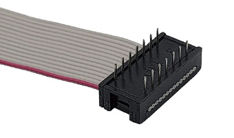
The first place to investigate is usually the connection between the conductor and the connector. With an IDC ribbon cable, reliable termination depends on each contact reaching the correct conductor at the correct position.
What happens when IDC contacts do not seat correctly?
IDC termination avoids individually stripping every conductor. The contact cuts through the insulation and establishes the electrical connection during the pressing operation. This makes assembly efficient, but it also means alignment and pressing consistency matter.
If the ribbon cable enters the connector at an angle, if the press does not close completely, or if the conductor spacing does not match the IDC contact spacing, one position can remain marginal while the rest appear normal. The result may not be a permanent open circuit. It can show up as an intermittent fault when the assembly moves.
A useful inspection therefore goes beyond checking whether the connector looks closed. Pin continuity, conductor alignment, connector seating, and cable retention should be checked together.
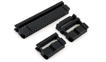
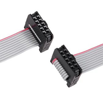
LEOCABLE supports several IDC constructions for different board layouts. Buyers working with standard industrial spacing can review the 2.54mm IDC flat cable assembly, which supports 6–64P configurations with UL2651 28AWG flat cable.
Why can a cable work during inspection but fail later?
A marginal termination can survive a static continuity test. Once the cable is folded into a chassis or the equipment starts vibrating, mechanical movement changes the pressure around the weak contact.
That is why pull retention and connector-exit inspection matter. A cable should not depend on the electrical contact itself to absorb repeated mechanical loading. Where the connector design provides a locking or strain-relief structure, it should be fully engaged before the assembly is approved.
Can the Wrong Pitch Create a Hidden Connection Problem?
Pitch errors are easy to underestimate because two IDC connectors can look similar in photographs or even in a quick incoming inspection.
Why must cable pitch and connector pitch be treated separately?
The pitch identified for a ribbon cable connector does not automatically equal the spacing between individual conductors in the cable.
For example, a 2.54mm double-row IDC system normally works with contacts arranged so that adjacent conductors in the flat cable are spaced more closely. Likewise, smaller 2.0mm and 1.27mm systems require their own compatible cable spacing.
This becomes important when a project changes connector families during development. Keeping the same pin count does not guarantee that the original cable, PCB header, IDC socket, and assembly tooling can remain unchanged.
LEOCABLE’s IDC flat cable range covers multiple connection formats, including 2.54mm, 2.0mm, 1.27×1.27mm, and 1.27×2.54mm options. Engineers comparing several layouts can explore LEOCABLE IDC flat cable configurations before freezing the PCB and cable drawing.
Can the pin map be wrong even when every conductor has continuity?
Yes. Continuity only proves that an electrical path exists. It does not prove that the path reaches the intended pin.
Pin 1 orientation, conductor order, straight-through wiring, and crossover wiring should be defined before production. A reversed connector or incorrectly mirrored drawing can produce a cable in which every conductor is electrically continuous but several signals arrive at the wrong destination.
The red reference edge commonly used on grey ribbon cable helps establish orientation, but it is not a substitute for an approved pin map.
Where serial or control signals are involved, TX, RX, ground, and any handshake conductors should be checked against the mating equipment rather than inferred from connector appearance.
Why Does Routing Damage Flat Cable Assemblies?
Flat construction is useful because conductors remain organized in a low-profile format. That same geometry, however, can tempt installers to fold the cable sharply just to clear an enclosure wall.
What happens when the bend starts too close to the connector?
The connector exit is already a mechanically sensitive region. A tight fold immediately after the housing concentrates stress where the cable meets the termination.
The problem becomes more serious when the cable is repeatedly opened and moved during service. What was acceptable during the first installation may become an intermittent connection after several maintenance cycles.
A better drawing defines not only overall cable length but also the exit direction and the space available for the first bend. In crowded equipment, a few millimeters of routing clearance can be more important than simply making the cable shorter.
Can enclosure hardware damage a ribbon cable over time?
Yes. Sheet-metal edges, covers, mounting posts, fans, heat sinks, and adjacent harnesses can all become wear points.
A ribbon cable that is pinched under a cover may still function when the unit leaves assembly. Repeated thermal movement or vibration can then damage the insulation. Abrasion can eventually expose or weaken a conductor.
Visual inspection should therefore include the installed route, not only the loose cable assembly.
For applications requiring a compact connection with a smaller interface, LEOCABLE also offers a 2.0mm IDC configuration using UL2651 28AWG PH1.0mm grey flat cable, reinforced locking, configurable length, and 6–60P options. Buyers can check the 2.0mm IDC cable configuration when board space and connector retention are both part of the project.
When Is EMI Actually the Cause of the Failure?
Interference often gets blamed whenever an industrial signal becomes unstable. Sometimes that diagnosis is correct. Sometimes the real issue is a poor contact, damaged conductor, wrong grounding arrangement, or incorrect pin assignment.
What should be checked before adding shielding?
First reproduce the fault.
If the problem appears when a motor starts, an inverter changes speed, a relay switches, or a power supply enters a different load condition, electromagnetic interference deserves closer investigation.
Then compare that behavior with connector contact, grounding, cable route, and pin mapping. Shielding should solve an identified exposure problem rather than cover an unresolved assembly fault.
For a detailed comparison, engineers can see when shielded ribbon cable is worth using.
What changes when a shielded cable is selected?
Shielding introduces another production variable. Coverage must remain intact, the cable must still fit the available routing space, and any required grounding or termination method has to be defined.
A cut, loose section, or poorly controlled shield termination can reduce the intended benefit. The finished cable should therefore be inspected after assembly and again in the equipment route.
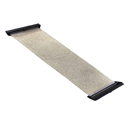
LEOCABLE’s shielded IDC flat flexible cable supports 06–80P configurations with several IDC pitch and wire-spacing options. Conductive fabric wraps the cable to add shielding and abrasion protection, while cable length can be adjusted around the equipment layout.
What Should Buyers Check Before Approving a Sample?
A good sample approval process removes uncertainty before quantity increases.
Which specifications should be frozen first?
The drawing or RFQ should define at least:
|
Item |
Apa yang perlu dikonfirmasi |
|
Konektor |
type, pitch and pin count |
|
Cable |
conductor pitch, wire specification and length |
|
Wiring |
Pin 1, orientation and full pin map |
|
Termination |
IDC structure and locking requirement |
|
Routing |
exit direction and critical bend locations |
|
Lingkungan |
vibration, temperature and EMI exposure |
|
Inspection |
continuity and mechanical checks |
If the mating PCB or device is already fixed, providing its connector information can prevent a cable specification from being built around assumptions.
Length also deserves more attention than it normally receives. Excess cable may be folded into a small enclosure, while a cable that is too short puts constant tension on the connector.
Why should the sample be tested inside the actual equipment?
Bench inspection answers only part of the question.
The sample should be installed in the intended route and checked while the equipment operates under realistic conditions. That can reveal pressure from a cover, connector movement, interference near a drive, or insufficient service clearance.
If the application involves repeated maintenance, unplugging and reinstallation should also be considered during the validation stage.
This type of review is where custom manufacturing becomes useful. Rather than forcing one standard cable into every chassis, LEOCABLE can adjust length, pin count, pitch, wiring definition, and selected connector structures around the equipment design.
How Can Production Prevent the Same Failure From Returning?
Once a sample is approved, production control becomes a repeatability problem.
Why does a golden sample matter?
The approved assembly gives operators and inspectors a physical reference for connector orientation, cable direction, dimensions, markings, and workmanship.
It should be supported by a controlled drawing. If production relies only on operator memory, straight-through and crossover definitions, Pin 1 direction, or connector orientation can drift between batches.
The first production pieces should be checked against that approved standard before the entire order is released.
Which inspections are worth keeping in every batch?
Pin continuity is essential, but it should not stand alone.
Inspection should also cover connector seating, pin mapping, visible insulation damage, cable length, terminal or connector retention, and any specified shielding treatment. When the assembly includes a critical mechanical connection, a suitable retention or pull check can expose weak termination before the cable reaches the equipment.
LEOCABLE combines cable and connector manufacturing support with configurable IDC assemblies rather than limiting buyers to one fixed pitch or pin count. This gives OEM projects more room to match the interconnect to the PCB, enclosure, service route, and production method.
When a project already has a drawing, sample, pin map, or problem cable, buyers can send the cable requirements to LEOCABLE for review before locking the next production run.
Kesimpulan
Ribbon cable assemblies rarely fail for only one reason. A stable assembly depends on the connector pitch matching the cable, correct IDC termination, an accurate pin map, enough mechanical relief around the connector, a suitable routing path, and realistic equipment testing.
The most effective troubleshooting sequence is therefore simple: verify the electrical connection first, confirm the wiring definition, inspect the installed mechanical route, and investigate EMI only when the failure pattern supports it. Once the design works, repeatable inspection keeps the same problem from returning in production.
For OEM equipment, treating the ribbon cable as part of the complete interconnect system rather than as a commodity wire makes sample approval faster and gives both engineering and procurement teams clearer criteria for the next order.
Pertanyaan yang Sering Diajukan (FAQ)
Q1: What causes intermittent connections in ribbon cable assemblies?
A1: Intermittent connections commonly come from incomplete IDC termination, misaligned conductors, weak connector retention, repeated bending near the connector, insulation damage, or movement after installation. Checking only continuity may miss a marginal contact that changes when the cable is flexed.
Q2: Can a ribbon cable fail even if it passes a continuity test?
A2: Yes. A continuity test confirms that a conductive path exists at the time of testing. It does not confirm correct pin mapping, installed routing, mechanical retention, EMI performance, or whether a weak contact remains stable during vibration and equipment operation.
Q3: What should buyers specify before ordering a custom IDC ribbon cable?
A3: Buyers should define connector type, pitch, pin count, cable specification, conductor spacing, finished length, Pin 1 orientation, complete pin map, connector exit direction, locking requirements, operating environment, and required inspections. Providing mating connector or PCB information also helps reduce specification errors.