Masalah Kabel Data SATA di Ruang Drive yang Sempit: Kapan Konektor Sudut Kanan Membantu
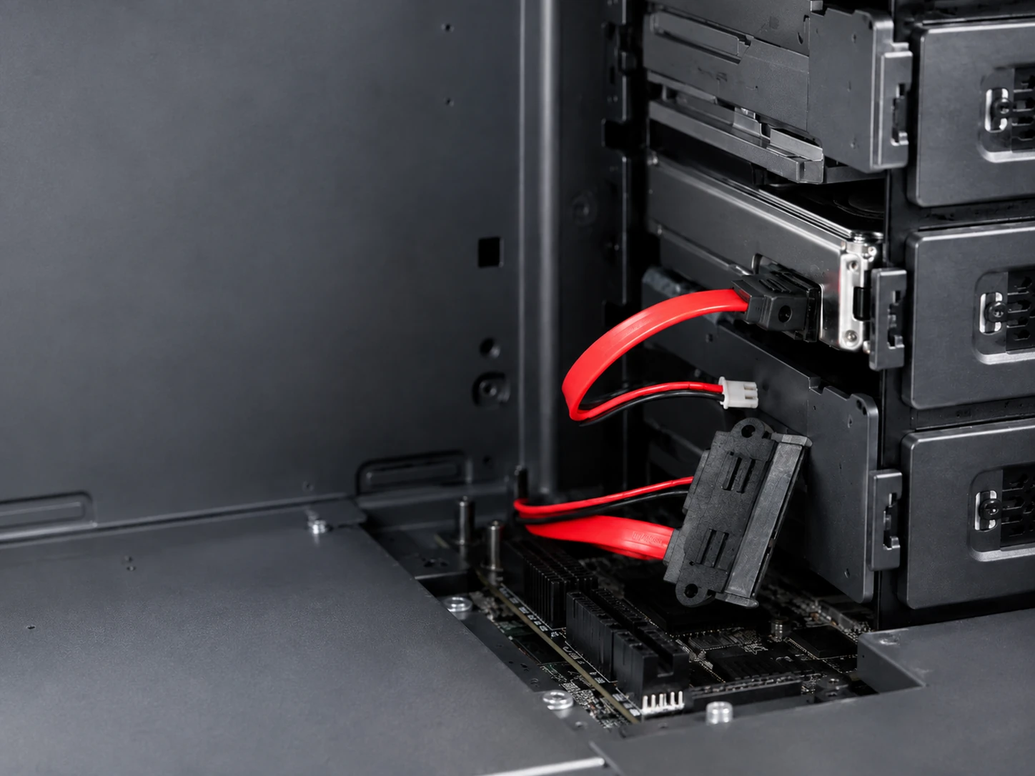
Satu drive penyimpanan saja dapat membuat penyelesaian casing yang tadinya rapi menjadi sangat sulit. Papan sudah terpasang, catu daya sudah terpasang, dan ruang drive tampak bersih sampai penutupnya ditutup. Kemudian konektor menempel pada panel, kabel harus berbelok terlalu tajam, atau kabel daya dan kabel data bersaing untuk mendapatkan jalan keluar yang sempit.
Kabel data SATA seringkali disalahkan ketika sebuah drive hilang selama perakitan atau sulit diganti di kemudian hari. Namun, dalam unit yang ringkas, kabel hanyalah salah satu bagian dari keputusan tersebut. Posisi port SATA, lokasi sumber daya, arah keluaran konektor, dan ruang yang tersisa untuk teknisi semuanya penting. Kabel daya SATA dapat menimbulkan tekanan yang sama dari sisi berlawanan dari drive.
Pertanyaan yang bermanfaat bukanlah sekadar, “Apakah colokan ini cocok?” Melainkan apakah jalur yang telah selesai menyisakan ruang yang cukup agar penutup dapat tertutup, menghindari tekukan paksa pada konektor, dan tetap memungkinkan seseorang untuk melepaskan drive tanpa harus membongkar setengah dari peralatan. Di situlah tata letak 7+15P, adaptor terpisah, atau keluaran siku-siku menjadi pilihan desain yang praktis, bukan sekadar detail katalog.
Mengapa Ruang Hard Disk yang Sempit Mengubah Kabel Sederhana Menjadi Masalah Servis?
Masalah ruang biasanya muncul setelah gambar disetujui. Sebuah drive mungkin terletak dekat dengan panel vertikal, penutup kipas, drive kedua, atau modul daya. Steker lurus yang tampak tidak berbahaya dalam tata letak tampilan atas dapat mendorong kabel ke dalam penutup atau memaksa kawat untuk terlipat tepat di badan konektor.
Tekanan tersebut tidak selalu menyebabkan kerusakan seketika. Tekanan itu dapat memperlambat perakitan awal, membuat kabel terus-menerus terbebani sisi samping, atau mengubah penggantian drive rutin menjadi pekerjaan servis yang sulit. Semakin sering penutup dibuka, semakin penting jalur tersebut. Jalur kabel harus memungkinkan konektor masuk lurus, berbelok secara bertahap setelah penutup, dan tetap cukup terlihat agar teknisi dapat melacaknya.
Inilah mengapa pengukuran jarak yang kecil lebih berguna daripada spesifikasi kabel umum. Ukur dari antarmuka SATA ke penghalang terdekat, lalu tandai arah keluarnya kabel dari drive. Periksa juga jalur tersebut dengan penutup terpasang. Ruang yang tersedia berubah saat casing tertutup, dan jalur servis seringkali berbeda dari jalur perakitan.
 Mulailah dengan Jalur Data, Jalur Daya, dan Arah Konektor.
Koneksi data dan koneksi daya memiliki fungsi yang berbeda. Kabel SATA 7 pin membawa jalur data ke pengontrol. Konektor daya SATA memasok daya ke drive dari sistem daya peralatan. Menganggap keduanya sebagai satu "kabel SATA" yang samar memudahkan terjadinya konflik ruang atau menentukan adaptor yang salah.
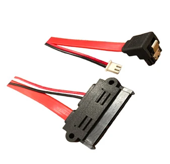
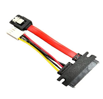
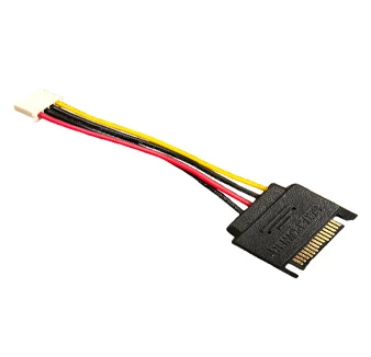
LUONYX menawarkan beberapa SATA membentuk yang membuat pilihan-pilihan tersebut tetap terlihat pada gambar. Itu Kabel Tetap Sudut Kanan Profesional SATA 7 15P Menggabungkan antarmuka data 7-pin 90 derajat dengan antarmuka daya 15-pin, sehingga kedua koneksi dapat keluar dari drive dalam satu arah yang ditentukan. Jika sumber daya peralatan menyediakan antarmuka Molex 4-pin, maka Professional SATA Kabel Adaptor Kombinasi Data dan Daya menyediakan antarmuka data dan daya SATA dengan transisi daya Molex tersebut. Spesifikasi SATA Revisi 3.0 (6Gbps) merupakan titik kompatibilitas jalur data; ini tidak menggantikan kebutuhan untuk memeriksa pengontrol, drive, dan jalur akhir secara bersamaan.
Konektor 7-pin dan 15-pin berbeda.
Mulailah dengan menandai lokasi pengontrol dan sumber daya pada gambar yang sama. Kabel data harus mencapai pengontrol tanpa melewati tepi yang tajam atau terjebak di bawah rakitan lain. Kabel daya membutuhkan jalur tersendiri dari sumber daya, dengan kelonggaran yang cukup untuk pemasangan tetapi tidak terlalu panjang sehingga harus dilipat ke dalam ruang pemasangan.
Ketika kedua jalur dimulai dari sisi berlawanan dari area tertutup, kabel terpisah dapat mempermudah inspeksi. Ketika keduanya harus keluar dari sisi area tertutup yang sama, jalur gabungan 7+15P dapat mengurangi kepadatan. LUONYX juga menyediakan rakitan kabel daya SATA dengan konektor jantan 15 pin, yang memberikan opsi jalur daya terpisah ketika tata letak tidak memerlukan perakitan gabungan. Jawaban yang tepat berasal dari tata letak peralatan, bukan dari preferensi untuk jumlah komponen yang paling sedikit.
Ketika rute gabungan lebih mudah dikendalikan
Koneksi gabungan tidak otomatis lebih baik, tetapi dapat menyederhanakan jalur yang jika tidak akan berisi dua konektor yang bersaing untuk celah yang sama. Hal ini perlu dipertimbangkan ketika braket penyimpanan menahan posisi drive, sumber daya berada di dekatnya, dan kabel data harus keluar searah dengan kabel daya.
Keputusan tersebut harus tetap mempertimbangkan aspek mekanis maupun elektrik. Konfirmasikan sisi drive mana yang membutuhkan ruang bebas, bagaimana kabel keluar, dan apakah antarmuka daya dapat dilepas dengan akses jari biasa. Kemudian, cocokkan antarmuka daya sisi sumber dengan bentuk kabel: koneksi daya sisi drive 15-pin, atau transisi Molex 4-pin jika peralatan membutuhkannya. Jalur yang hanya pas sebelum penutup dipasang bukanlah jalur yang sudah selesai.
Pilih Jalur Kabel Sebelum Memilih Panjang Kabel
Panjang kabel biasanya dicantumkan terlalu awal dalam permintaan. Sebelum memilih angka, tentukan di mana kabel akan berbelok, di mana kabel akan diikat, dan di mana kabel harus dicabut. Kabel yang terlalu pendek dapat menarik konektor ke samping. Kabel yang terlalu panjang harus disimpan di suatu tempat, seringkali di samping kipas, modul daya, atau panel servis yang dapat dipindahkan.
Jalan keluar lurus dan siku-siku memecahkan masalah ruang bebas yang berbeda.
Kabel SATA siku-siku menjadi pilihan tepat ketika kabel lurus akan menabrak dinding atau memaksa tekukan tajam pada antarmuka. Ini bukan peningkatan universal. Jika ruang kosong yang tersedia berada di atas drive dan bukan di sampingnya, konektor lurus mungkin memberikan jalur yang lebih rapi. Kuncinya adalah arah keluar setelah penyambungan, bukan daya tarik visual konektor tersebut.
Gunakan prototipe sederhana sebelum memesan dalam jumlah besar. Tempatkan hard drive di braket akhirnya, sambungkan steker yang sesuai, tutup penutupnya, dan periksa apakah jalur kabel tetap lurus. Ulangi pemeriksaan dengan hard drive yang akan dilepas. Jika konektor perlu ditarik ke samping atau pengikat kabel harus dipotong untuk memperbaiki hard drive, jalur tersebut perlu diperiksa ulang.
Untuk lokasi penyimpanan tetap, Kabel Tetap Sudut Kanan Profesional SATA 7 15P menyediakan jalur keluar sisi data 90 derajat dengan antarmuka daya 15-pin dalam satu rakitan. Hal ini memberi tim teknik bentuk produk konkret untuk dievaluasi terhadap jarak braket dan penutupnya, alih-alih mencoba menilai jalur dari gambar konektor generik. Ini juga memisahkan pertanyaan tentang arah konektor dari pertanyaan apakah sumber daya memerlukan koneksi SATA langsung atau adaptor Molex 4-pin.
Ubah Sampel Menjadi Cek Siap Produksi
Sampel tersebut harus mereproduksi jalur yang akan digunakan unit produksi. Ujilah di dalam wadah sebenarnya, dengan model drive, braket, catu daya, penutup, dan semua kabel yang berdekatan terpasang. Kabel yang pas di meja terbuka belum menjawab pertanyaan sulit tersebut.
Selama perakitan sampel, sambungkan sisi data 7-pin ke jalur pengontrol, sambungkan sisi daya 15-pin ke drive, dan tutup penutup untuk memastikan bahwa keluaran 90 derajat tidak terhalang. Jika adaptor data dan daya ditentukan, verifikasi koneksi sumber Molex 4-pin. Kabel juga harus diikat tanpa terjepit dan tetap dapat dilepas selama servis.
Untuk permintaan informasi, berikan model penggerak atau orientasi antarmuka, sketsa rute sederhana, jarak bebas pada sisi terbatas ruang pemasangan, panjang akhir yang dibutuhkan, antarmuka data sisi pengontrol, antarmuka sumber daya, dan jumlah yang diharapkan. Detail tersebut memungkinkan untuk menilai apakah instalasi memerlukan jalur data dan daya terpisah, atau Formulir adaptor Molex-ke-SATAatau rakitan 7+15P sudut siku-siku tetap sebelum pengerjaan perkakas atau pekerjaan batch dimulai.
Kesimpulan
Dalam ruang drive bay yang sempit, keputusan mengenai kabel dimulai dari jalur kabel, bukan nama konektornya. Kabel data SATA memerlukan tinjauan ruang yang sama seperti jalur dayanya. Jalur data dan daya yang terpisah dapat lebih mudah diperiksa; jalur gabungan 7+15P dapat lebih mudah dikontrol karena keduanya harus keluar dari sisi drive yang sama. Pilihan tersebut bergantung pada ruang yang sebenarnya, arah keluar, dan akses servis.
Sebelum beralih dari gambar ke pesanan massal, tinjau rute dengan penutup tertutup dan perhatikan jalur pelepasan drive. Untuk proyek yang membutuhkan kabel daya SATA, adaptor, atau kabel SATA siku, kirim LUONYX Orientasi penggerak, ruang bebas yang tersedia, antarmuka daya, panjang jalur, dan jumlahnya. Hal itu memberikan tinjauan kabel sebuah instalasi nyata untuk dijadikan acuan.
Pertanyaan yang Sering Diajukan (FAQ)
Q1: Apakah kabel SATA 7 pin sama dengan kabel daya SATA?
A1: Tidak. Kabel SATA 7 pin membawa koneksi data. Koneksi daya menggunakan antarmuka 15 pin. Peralatan dengan drive penyimpanan biasanya membutuhkan kedua fungsi tersebut, baik sebagai jalur terpisah atau dalam rakitan gabungan 7+15P.
Q2: Kapan saya harus menggunakan konektor siku?
A2: Gunakan kabel SATA siku-siku bila konektor lurus akan langsung menancap ke panel, penutup, atau komponen yang berdekatan. Pertama, pastikan arah keluarnya kabel, ruang di belakang drive, dan jalur setelah penutup ditutup.
Q3: Apa yang dibutuhkan untuk permintaan konektor daya SATA?
A3: Berikan informasi mengenai orientasi penggerak, panjang jalur, jarak bebas terbatas, antarmuka sumber daya, arah keluar, jumlah, dan apakah diperlukan perakitan gabungan.