

Table des matières
Nouvelles connexes
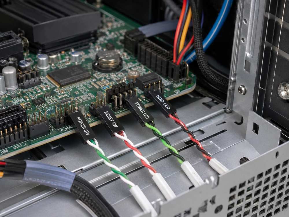
Shielded vs Unshielded Ribbon Cable: When Does EMI Protection Matter?
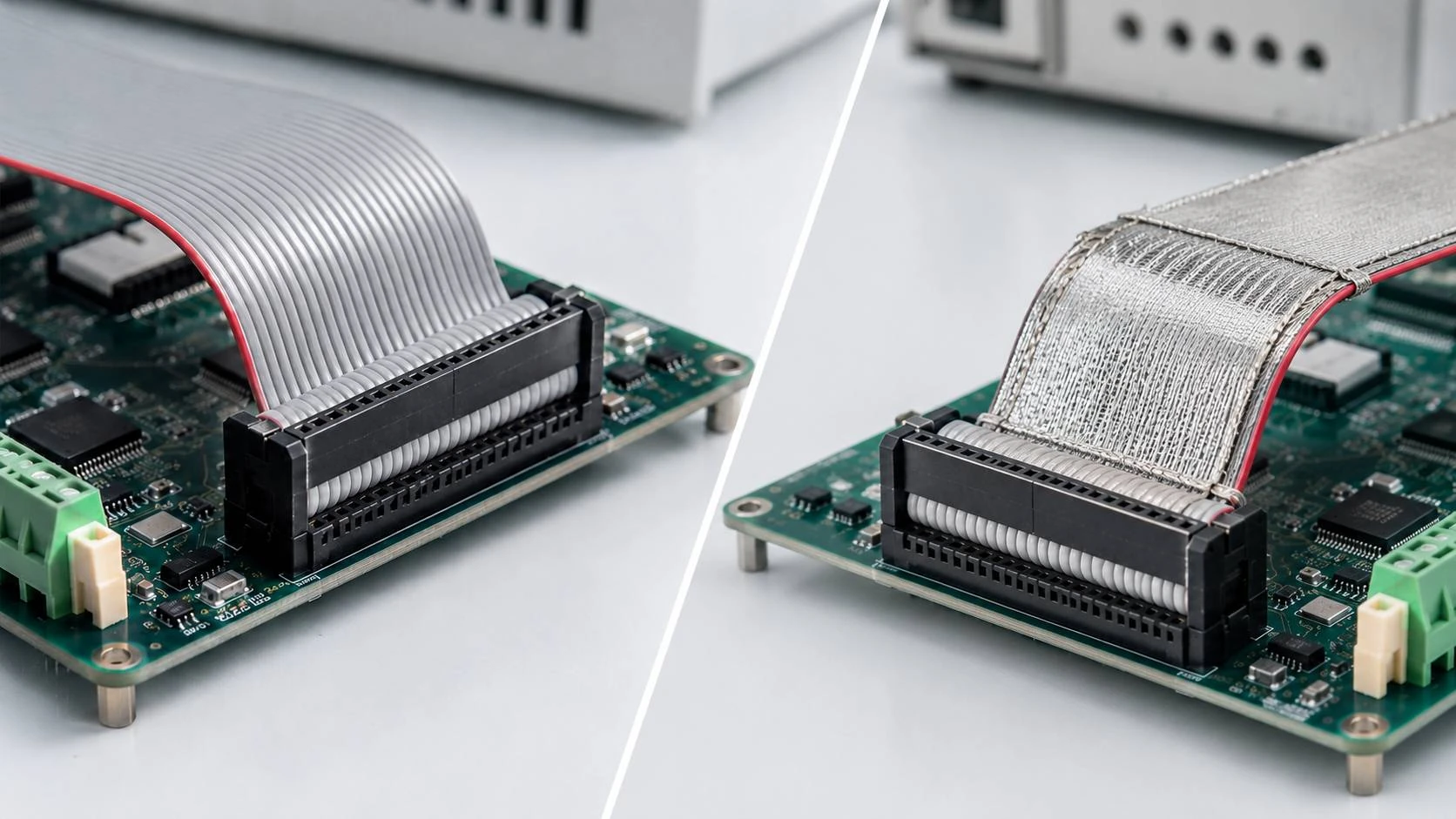
A signal fault that appears when a motor starts or a drive changes speed can lead buyers to blame the cable. Yet the cause may also involve pin mapping, contact quality, grounding, routing, or circuit design. Adding shielding too early may increase cost without correcting the fault.
Assess the noise source, signal sensitivity, cable route, enclosure, and test conditions together. A shielded ribbon cable can help in equipment exposed to electromagnetic interference, while a standard flat cable may be better for a short, controlled internal connection. The installed environment should guide the decision.
What Changes When a Ribbon Cable Is Shielded?
Shielding adds a conductive layer around or over the conductors. This affects the way external noise couples into signal lines, the space required for routing, bend behavior, and the checks needed during production.
The Shield Helps Control Electromagnetic Coupling
Electrical noise can couple into nearby conductors through electric or magnetic fields. A conductive layer may reduce this coupling by providing a controlled path for induced current and limiting radiation from the cable itself. The result depends on shield material, coverage, frequency, cable length, termination, and equipment grounding.
Cable shielding should not be described as a complete barrier. Open areas, damaged coverage, long unshielded ends, or an undefined grounding path can reduce its practical value. The finished assembly should be tested inside the operating equipment, especially when it carries sensor data or control signals with limited noise margin.
Shielding Adds Design and Inspection Requirements
A conductive wrap adds details that must be defined before production. The drawing should show where the shield starts and ends, whether it connects to a chassis or grounding point, and how the termination is protected. Added thickness near bends must also be considered.
Inspection must cover more than pin continuity. The conductive layer should remain complete, without cuts, gaps, or loose sections. Any ground connection must match the approved drawing. These steps are justified only when shielding addresses a real need.
When Is an Unshielded Cable Usually Sufficient?
Many internal connections operate reliably without an added conductive layer. A simpler construction reduces bulk, supports easier routing, and removes shield termination from production. It is designed for a different electrical environment.
Short Internal Runs in a Controlled Enclosure
A standard idc cable is often suitable when the route is short, fixed, and separated from major noise sources. Signal level, circuit design, enclosure, and PCB layout should provide enough operating margin. Stable prototype and installed-equipment results offer stronger evidence than assumptions based only on the industry.
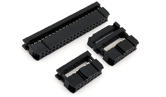
Le Ensemble de câble plat IDC professionnel 2.54MM uses UL2651 28AWG tinned-copper flat cable with 1.27mm conductor pitch. It supports 6–64P configurations and uses 2.54mm IDC connectors at both ends. Black PBT engineering-plastic housings include a foolproof structure for correct orientation. The operating range is -20°C to +80°C, and the assembly is RoHS compliant.
This configuration suits repeated internal connections after the route and signal environment have been verified. Its fixed conductor order also supports clear pin mapping across flat cable assemblies.
Stable Routing Away From Major Noise Sources
Cable placement matters even when no shield is used. A flat signal cable should not run for a long distance beside motor leads, inverter outputs, or switching power conductors when another route is available. Separation and crossings should be planned at equipment level.
A standard construction may be sufficient when the route remains consistent between units and the system passes testing under realistic loads. Tests should include startup, switching, speed changes, or peak load. A static continuity check alone does not confirm performance inside the enclosure.
When Should Buyers Evaluate a Shielded Construction?
A shielded option becomes more relevant when sensitive signals follow a route that cannot remain clear of electrical noise. It may also help when related equipment models use different layouts and the distance from noise sources varies.
Sensitive Signals Near Drives or Power Electronics
Industrial equipment may place signal wiring near variable-frequency drives, power supplies, motors, relays, or switching modules. These sources increase the need for careful routing and validation. An error that follows motor speed, switching frequency, or load is a stronger reason to investigate electromagnetic interference.
Before changing the cable, confirm connector contact, signal reference, pin assignment, and grounding. Once those checks are complete, a shielded ribbon cable can be tested as one part of the control plan rather than as a substitute for correcting another fault.
Longer or Less Predictable Internal Routes
Longer routes provide more opportunity for coupling, especially when the cable crosses several modules or passes through a crowded enclosure. A route that is acceptable in one model may run close to a noise source in another.
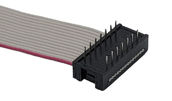
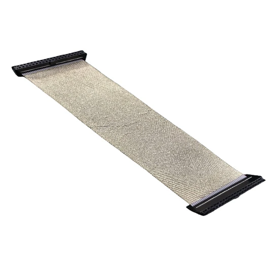
Le Ensemble de câble flexible plat IDC professionnel supports 06–80P configurations, with 2.54mm, 2.0mm, 1.27 × 1.27mm, and 1.27 × 2.54mm interface options. Wire spacing can be PH1.27mm, PH1.0mm, or PH0.635mm. Conductive fabric wraps the gray cable to enhance shielding and wear resistance, while cable length can be adjusted for the equipment layout. It is RoHS compliant.
The available pitch and pin options allow this shielded idc cable to fit different connector layouts without changing the flat-cable routing concept. The conductive fabric does not remove the need to confirm coverage, end treatment, and any required ground connection during sample approval.
Why Can Shielding Fail to Solve a Signal Problem?
Choosing a shielded construction is only one part of the project. Performance may remain unstable when the shield is incomplete, incorrectly terminated, or used to address a fault caused elsewhere in the circuit.
The Conductive Layer Is Damaged or Incomplete
Cuts can occur during cable preparation, while scratches or loose wrapping may develop during handling. Coverage can also stop too far from the connector, leaving an exposed section near a noise source.
Finished inspection should verify the specified coverage along the full route. Bend areas and connector exits deserve attention because they experience more movement. The wrap should remain secure after installation without forcing the cable into an unapproved bend.
The Grounding Path Is Not Defined
A shield intended to connect to ground needs a defined electrical and mechanical path. The drawing should identify the connection point and required end treatment. Leaving this decision to assembly operators can produce inconsistent grounding within the same order.
The correct grounding approach depends on equipment design, frequency environment, and system reference. Production inspection should confirm that the approved connection is present and secure. Where no ground connection is required, the drawing should state this clearly. Incomplete shield coverage, physical damage, loose termination, and improper grounding can all weaken anti-interference performance.
Shielded and Unshielded Options at a Glance
|
Project factor |
Standard flat cable |
Shielded flat cable |
|
Typical environment |
Controlled internal wiring |
Routes with higher EMI exposure |
|
Cable structure |
Flat conductors without added wrap |
Flat conductors with a conductive layer |
|
Routing requirements |
Generally simpler |
Added thickness must be considered |
|
Grounding definition |
Usually not part of the cable structure |
Must be defined when required |
|
Main inspection points |
Pitch, pin map, orientation, IDC contact |
Standard checks plus shield coverage and termination |
|
Suitable use |
Stable short routes |
Sensitive or interference-prone routes |
|
Production complexity |
Generally lower |
Additional processing and inspection |
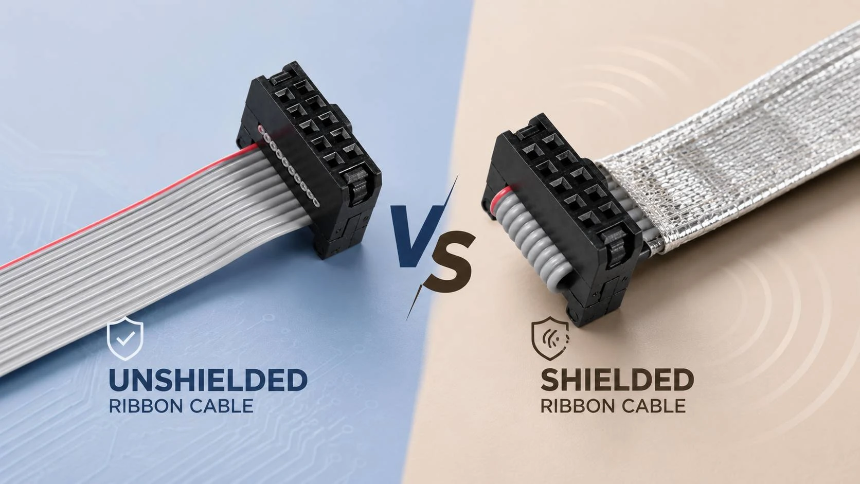
The standard option simplifies controlled internal wiring and may need less space near connectors. The shielded option adds protection for higher-risk environments but also introduces inspection, routing, and grounding questions.
For flat cable assemblies, selection should consider signal type, route length, nearby power electronics, enclosure construction, connector pitch, bend points, and equipment test results. Cost matters, but it should follow the technical assessment. Added shielding without a defined need may create unnecessary complexity.
What Should Buyers Specify Before Sample Production?
A useful request should include connector type, pin count, IDC pitch, conductor spacing, finished length, Pin 1 orientation, and the full pin map. The equipment drawing should show the installed route and the position of motors, drives, power supplies, relays, and high-current conductors.
For a shielded idc cable, also define the conductive material, coverage area, end treatment, and grounding requirement. State the expected bend route and abrasion points. Inspection may include pin continuity, contact resistance, connector orientation, shield integrity, and verification of the ground connection where applicable.
The sample should be tested in the operating states that create the highest noise, such as startup, rapid switching, load changes, or maximum speed. Comparing standard and shielded versions under the same conditions provides better evidence than relying on construction alone.
Choose Shielding From the Equipment Environment
An unshielded design is not automatically inadequate, and a shielded ribbon cable is not a universal upgrade. The right choice follows the signal, route, noise source, grounding plan, and validation result. Standard and shielded flat cable assemblies can both be reliable when their construction matches the equipment.
Have a pin map, cable route, or suspected interference source ready for review? Share the equipment requirements with LEOCABLE before sample production so the cable structure, connector pitch, and inspection points can be checked against the installation.
FAQ (questions fréquentes)
Q: Does every industrial flat cable need shielding?
A: No. A standard idc cable may suit short, controlled routes that remain away from major noise sources and pass installed-equipment testing. Shielding becomes more relevant when signals are sensitive or routing cannot avoid drives, motors, switching modules, or other interference sources.
Q: Can a shielded cable work without grounding?
A: It depends on the shield construction and system design. If the shield is intended to connect to ground, the connection point and end treatment must be defined. A conductive wrap should not be assumed to perform as expected when its electrical path is unclear.
Q: What should be tested before approving the assembly?
A: Check pin mapping, continuity, connector orientation, IDC penetration, cable length, and installed routing. For a shielded version, also inspect conductive-layer coverage, end treatment, physical damage, and the specified ground connection. Final testing should take place while the equipment operates under realistic noise conditions.