

Bảng nội dung
Tin tức liên quan
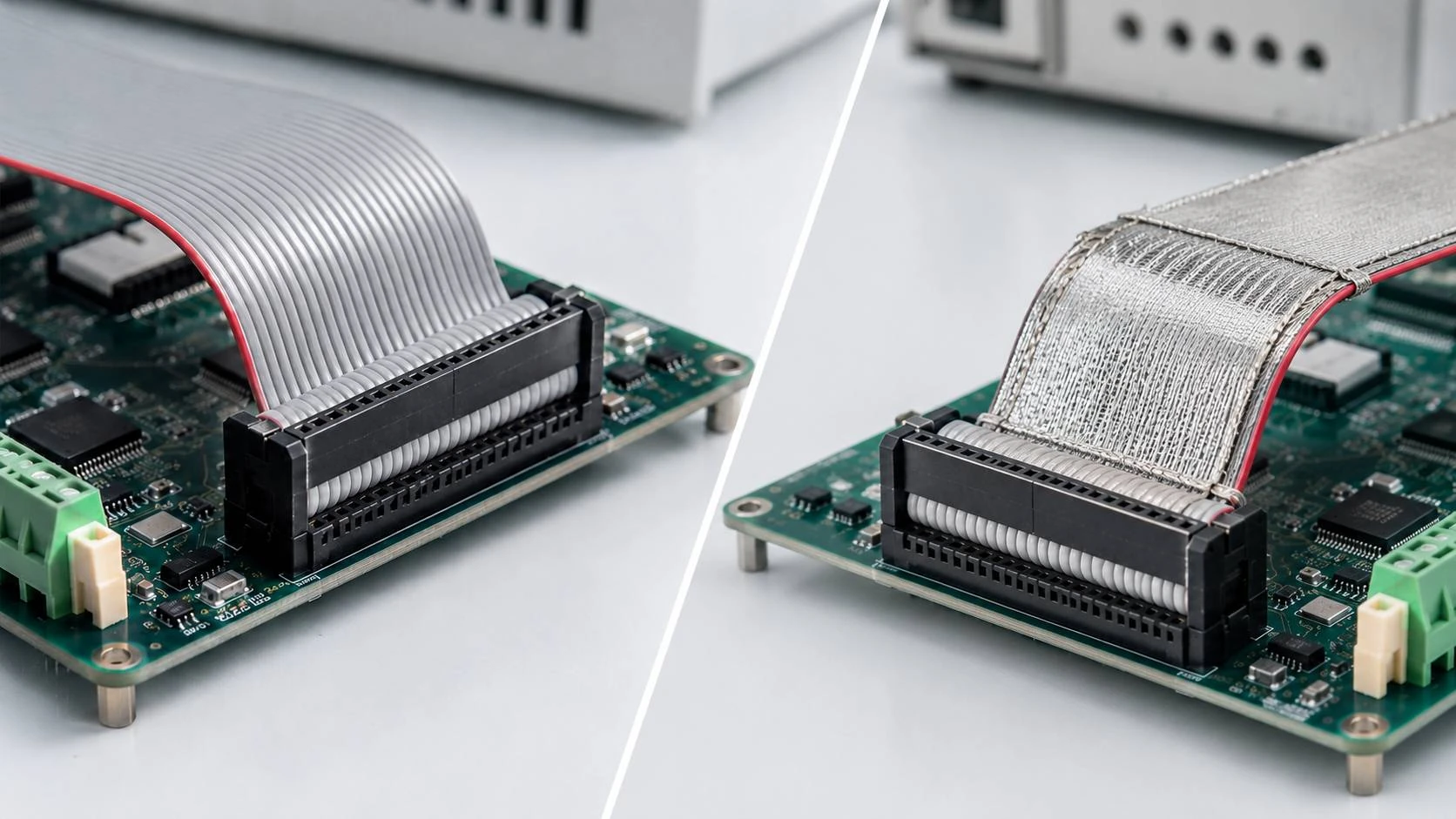
Vượt qua những thách thức khi làm việc với cáp dẹt
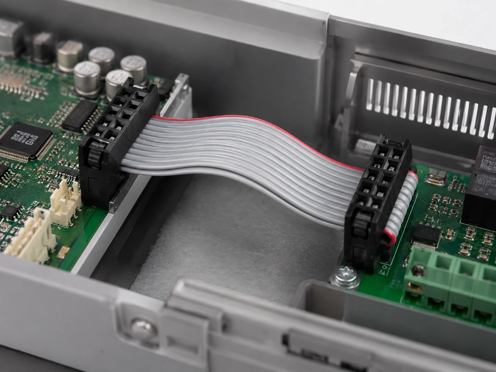
Hầu hết các sự cố về cáp dẹt đều có thể được ngăn ngừa trước khi lắp đặt. Những lỗi gây ra nhiều rắc rối nhất thường đến từ các đầu nối không phù hợp, hướng chân cắm đảo ngược, đấu nối IDC không hoàn chỉnh, định tuyến kém, ứng suất cơ học hoặc thông số kỹ thuật lắp ráp quá sơ sài.
Cáp dẹt rất hữu ích vì nó sắp xếp nhiều dây dẫn thành một bố cục mỏng và dễ dự đoán. Chính hình dạng đó có nghĩa là đầu nối, khoảng cách giữa các dây dẫn, đường dẫn và quy trình đấu nối phải hoạt động đồng bộ. Đối với các nhà sản xuất thiết bị và nhà tích hợp hệ thống, một cụm cáp dẹt đáng tin cậy bắt đầu từ việc kiểm soát các mối quan hệ đó thay vì coi cáp như một dây dẫn nội bộ thông thường.
Đối chiếu hình dạng đầu nối và sơ đồ chân cắm hoàn chỉnh.
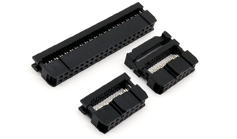
Cáp dẹt có vẻ đơn giản trên bản vẽ vì các dây dẫn của nó nằm trên một hàng phẳng. Khó khăn xuất hiện khi cáp đó phải kết nối với đầu nối IDC hai hàng. Khoảng cách giữa các dây dẫn của đầu nối và khoảng cách giữa các dây dẫn của cáp có liên quan với nhau, nhưng chúng không phải lúc nào cũng giống nhau về mặt số học.
Ví dụ, hệ thống ổ cắm IDC 1,27 x 1,27 mm của LUONYX sử dụng khoảng cách giữa các tiếp điểm đầu cuối khoảng 0,635 mm trên toàn bộ cáp, do đó cáp dẹt mật độ cao tương ứng sử dụng khoảng cách giữa các dây dẫn là 0,635 mm. Hệ thống IDC hai hàng 2,0 mm thường tương ứng với khoảng cách giữa các dây dẫn là 1,0 mm, trong khi ổ cắm IDC 2,54 mm thường hoạt động với khoảng cách giữa các dây dẫn của cáp dẹt là 1,27 mm. Nếu một kỹ sư đặt hàng ổ cắm IDC 2,0 mm và cho rằng cáp phải có khoảng cách giữa các dây dẫn là 2,0 mm, thì kết nối dịch chuyển lớp cách điện sẽ không chính xác.
Thông thường, đầu nối trên bo mạch in (PCB) sẽ được xác định. Sau khi xác định được phía thiết bị, hãy kiểm tra lại khoảng cách giữa các chân cắm IDC, số lượng vị trí, phương pháp phân cực và khoảng trống cần thiết trước khi hoàn thiện cáp. (LUONYX) Cáp dẹt IDC 2,54 mm là một ví dụ về cụm lắp ráp nên được lựa chọn từ giao diện đã được phê duyệt thay vì từ nguồn có sẵn chung.
Xác định chân số 1 ở cả hai đầu.
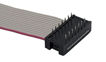
Cáp dẹt có thể được đấu nối hoàn hảo nhưng vẫn kết nối sai tín hiệu. Nhiều loại cáp sử dụng dây dẫn viền màu đỏ hoặc màu khác để xác định phía chân số 1, trong khi các đầu nối IDC có thể bao gồm dấu tam giác, vỏ có rãnh, vị trí ẩn hoặc các tính năng kết nối chống sai sót khác. Những tính năng đó hướng dẫn việc lắp ráp, nhưng chúng không tự xác định mạch điện.
Bản vẽ cần xác định rõ Chân 1 tại mỗi đầu nối và thể hiện đầy đủ mối quan hệ giữa hai đầu. Một số cụm lắp ráp là kiểu nối thẳng, với Chân 1 được nối với Chân 1. Một số khác yêu cầu kiểu nối chéo hoặc tùy chỉnh. Trường hợp bo mạch sử dụng kiểu chân cắm không chuẩn, dự án cần có bảng sơ đồ chân hoặc sơ đồ đấu dây cho mỗi dây dẫn, chứ không phải chỉ là hướng dẫn tuân theo màu dây cáp. Bản ghi này đặc biệt quan trọng khi các đầu nối tương tự phục vụ các phiên bản khác nhau của cùng một thiết bị.
Đảm bảo quá trình kết thúc IDC có thể lặp lại.
Công nghệ IDC hiệu quả vì mỗi tiếp điểm xuyên qua lớp cách điện và chạm đến dây dẫn chỉ trong một thao tác ép được kiểm soát. Có thể thực hiện việc đấu nối nhiều dây dẫn hoàn chỉnh mà không cần phải bóc vỏ từng dây một. Quá trình này nhanh chóng, nhưng vẫn nhạy cảm với sự thẳng hàng của cáp, độ sâu ép và sự phù hợp giữa tiếp điểm và cấu trúc cáp.
Nếu cáp được đưa vào đầu nối ở một góc, tiếp điểm có thể nằm gần mép của dây dẫn. Nếu quá trình ép không hoàn toàn, một hoặc nhiều tiếp điểm có thể không xuyên qua lớp cách điện đủ sâu. Cáp có thể vượt qua kiểm tra trực quan nhanh chóng nhưng lại phát sinh tín hiệu chập chờn khi được cầm nắm hoặc thiết bị rung động. Hướng dẫn sản xuất của LUONYX coi việc cáp IDC không xuyên qua hoàn toàn là một vấn đề về tiếp điểm: cần chuẩn hóa quy trình ép, xác minh việc lắp đặt hoàn toàn và kiểm tra tình trạng điện sau khi lắp ráp.
Việc lựa chọn cáp cũng quan trọng như việc kiểm soát áp suất. Cáp dẹt màu xám UL2651 28AWG được sử dụng rộng rãi cho hệ thống dây dẫn nội bộ có tổ chức, trong khi các hệ thống có khoảng cách giữa các dây dẫn nhỏ hơn có thể sử dụng cáp UL2678 30AWG với khoảng cách giữa các dây dẫn là 0,635 mm. Cụm bước răng 1,27 mm Phải sử dụng loại cáp và cấu trúc cách điện phù hợp với thiết kế của đầu nối IDC đã được phê duyệt. Bất kỳ sự thay thế nào về kích thước dây hoặc vật liệu cách điện đều phải được coi là thay đổi kỹ thuật, chứ không phải là quyết định mua hàng thông thường.
Lộ trình giúp giảm căng thẳng, chứ không chỉ là quãng đường ngắn nhất.
Cáp dẹt có thể giảm chiều cao dây dẫn và giữ nhiều mạch điện lại với nhau trong các hộp nhỏ gọn. Tuy nhiên, nó cũng có thể được đi dây không đúng cách. Các khúc uốn cong gấp ngay phía sau đầu nối, chuyển động lặp đi lặp lại tại điểm kết thúc và việc xoắn cáp để bù lại hướng đầu nối không chính xác đều tập trung ứng suất tại nơi các dây dẫn tiếp xúc với các điểm tiếp xúc.
Lên kế hoạch cho đường đi thực tế trước khi xác định chiều dài cáp cuối cùng. Bắt đầu với hai giao diện kết nối, sau đó theo dõi đường đi qua các giá đỡ, cạnh PCB, quạt, thiết bị lưu trữ, bảng điều khiển di động và các điểm cố định. Chiều dài hoàn thiện phải tuân theo lộ trình đó, chứ không phải là khoảng cách ngắn nhất giữa các đầu nối. Cáp ngắn có thể kéo đầu nối lệch sang một bên; cáp quá dài phải được cất giữ ở đâu đó, thường là bên cạnh quạt hoặc bảng điều khiển dịch vụ.
Giữ tải tránh xa đầu nối
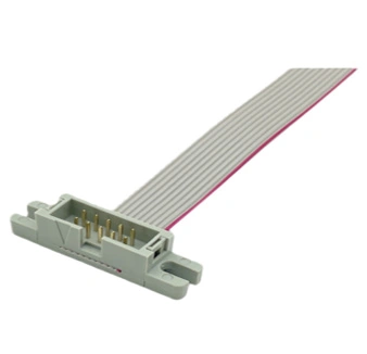
Đầu nối không nên chịu toàn bộ lực kéo tác động lên cáp. Trong các thiết bị được bảo dưỡng nhiều lần hoặc chịu rung động, các bộ phận giảm căng tích hợp, kẹp cáp hoặc các đặc điểm của khung máy nên giúp giảm tải trọng tác động lên dây dẫn và tiếp điểm. cụm đầu nối hộp IDC Có thể làm rõ hơn yêu cầu về việc lưu giữ đó trên bản vẽ lắp ráp đã được phê duyệt.
Các vấn đề riêng biệt về tiếp điểm, sơ đồ chân và lớp chắn.
Khi cáp dẹt truyền tín hiệu không ổn định, người ta thường đổ lỗi đầu tiên cho vật liệu cáp. Điều đó có thể dẫn đến việc khắc phục sai. Tiếp xúc đầu nối kém, lớp cách điện bị hỏng, kết nối chân cắm không chính xác, khoảng cách truyền dẫn quá xa, lớp chắn không đủ và tiếp đất kém là những nguyên nhân khác nhau cần các biện pháp khắc phục khác nhau.
Cần khắc phục sự tiếp xúc lỏng lẻo hoặc không hoàn chỉnh ở đầu dây. Sơ đồ chân cắm sai yêu cầu phải sửa lại dây dẫn. Lớp cách điện bị hư hỏng cho thấy có thể do cắt, thao tác hoặc định tuyến sai. Nhiễu điện từ có thể cần đến lớp chắn, nối đất hoặc cấu tạo cáp khác. Việc thêm lớp chắn vào một cụm lắp ráp kém chất lượng về mặt cơ học không giải quyết được vấn đề ban đầu.
Cáp dẹt tiêu chuẩn phù hợp với nhiều kết nối ngắn bên trong trong môi trường điện từ được kiểm soát. Việc chống nhiễu cần được chú trọng hơn khi đặt gần các bộ biến tần, nguồn điện cao tần, động cơ hoặc các tín hiệu nhạy cảm, và cần được đánh giá bằng phương pháp nối đất. Sản phẩm của LUONYX dẫn cáp ruy băng được che chắn Bài viết giải thích ranh giới quyết định mà không giả định rằng mọi cáp dẹt đều cần lớp chắn.
Viết bản đặc tả cáp trước khi lấy mẫu.
Nhiều vấn đề bắt nguồn từ yêu cầu không đầy đủ. Yêu cầu về cáp dẹt 20 chân với chiều dài nhất định chỉ cung cấp cho nhà máy một phần thông tin cần thiết để chế tạo sản phẩm chính xác. Một bản đặc tả chi tiết hơn sẽ xác định rõ loại đầu nối, khoảng cách giữa các chân giao diện, số vị trí, khoảng cách giữa các dây dẫn, cỡ dây, chiều dài hoàn thiện, hướng chân số 1, định nghĩa dây dẫn, hướng thoát của đầu nối, bộ phận giảm căng và bất kỳ yêu cầu nào về che chắn hoặc điều kiện môi trường.
Các yêu cầu kiểm tra cũng cần được bao gồm. Kiểm tra tính liên tục xác nhận đường dẫn điện dự định. Trường hợp ứng dụng có yêu cầu về điện trở tiếp xúc, tính toàn vẹn cách điện, hiệu suất kéo hoặc khả năng chắn, các yêu cầu đó phải được thể hiện trên bản vẽ hoặc tiêu chuẩn kiểm tra đã được phê duyệt. LUONYX hỗ trợ các cụm ổ cắm IDC 1,27 mm, 2,0 mm và 2,54 mm, các tùy chọn cáp dẹt UL2651 và UL2678, số lượng chân cắm, chiều dài và cấu hình cáp chuyên dụng theo ứng dụng được tùy chỉnh. Những lựa chọn này chỉ trở nên hữu ích sau khi các yêu cầu về thiết bị đã được xác định rõ ràng.
Ví dụ, một bộ điều khiển công nghiệp với đầu nối PCB 20 chân và không gian chiều dọc hạn chế cần phải xác nhận loại đầu nối tương thích. Sau đó, nhóm kỹ thuật sẽ chọn ổ cắm IDC và khoảng cách dây dẫn tương thích, xác định chân số 1 ở cả hai đầu, lập tài liệu sơ đồ tín hiệu và đo đường đi xung quanh bất kỳ cạnh nào của PCB. Trình tự đó làm cho mẫu thử có ý nghĩa vì cáp đang được kiểm tra dựa trên đường dẫn thực tế của thiết bị, chứ không phải là một mô tả không đầy đủ.
Phần kết luận
Cáp dẹt dễ gia công nhất khi thông số kỹ thuật của nó được xác định rõ trước khi sản xuất mẫu đầu tiên. Đầu nối và cáp phải khớp về mặt vật lý, hướng chân cắm phải khớp về mặt điện, và đường đi của cáp phải hợp lý về mặt cơ học. Việc kiểm tra đầu nối và lắp ráp hoàn chỉnh sau đó sẽ xác nhận rằng cụm cáp dẹt được sản xuất đúng như dự định.
Đối với thiết bị đặt làm riêng, vui lòng cung cấp bản vẽ đầu nối hoặc chân cắm PCB, sơ đồ chân, chiều dài yêu cầu, đường đi dây và môi trường ứng dụng. Liên hệ LUONYX Kiểm tra lại cụm cáp dẹt IDC và xác định các chi tiết cần sửa chữa trước khi sản xuất.
Câu hỏi thường gặp
Câu 1: Cáp dẹt có thể uốn cong hoặc gấp lại được không?
A1: Đúng vậy, nhưng hãy tránh những đoạn uốn cong gấp khúc không cần thiết, chuyển động lặp đi lặp lại và ứng suất tập trung gần đầu nối. Hãy lên kế hoạch cho đoạn uốn cong như một phần của bố trí thiết bị thay vì tạo ra nó trong quá trình lắp đặt cuối cùng để bù lại chiều dài cáp không chính xác.
Câu 2: Làm sao để biết đầu nối IDC có khớp với cáp dẹt hay không?
A2: Hãy kiểm tra loại đầu nối, khoảng cách giữa các chân tiếp xúc IDC, bước răng dẫn điện tương thích, cỡ dây, cấu trúc cách điện và số lượng chân cắm. Chỉ riêng bước răng tiếp xúc là chưa đủ. Ví dụ, ổ cắm IDC hai hàng 2,54 mm thường hoạt động với khoảng cách giữa các chân dẫn điện của cáp dẹt là 1,27 mm.
Câu 3: Nguyên nhân nào gây ra hiện tượng kết nối cáp dẹt không ổn định?
A3: Các nguyên nhân thường gặp bao gồm việc cắm cáp IDC không hoàn toàn, cáp bị lệch, dây dẫn hoặc lớp cách điện bị hư hỏng, ứng suất quá mức gần đầu nối, tiếp xúc kém hoặc cáp không phù hợp với thông số kỹ thuật của đầu nối. Hãy sử dụng cả kiểm tra thông mạch và kiểm tra cơ học để xác định nguyên nhân.