

Inhaltsverzeichnis
Verwandte Nachrichten
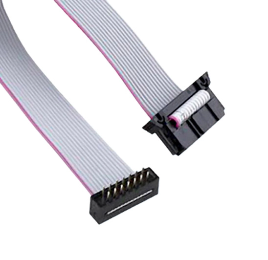
Why Does an RS232 Cable Drop Its Signal Only When the Machinery Runs?
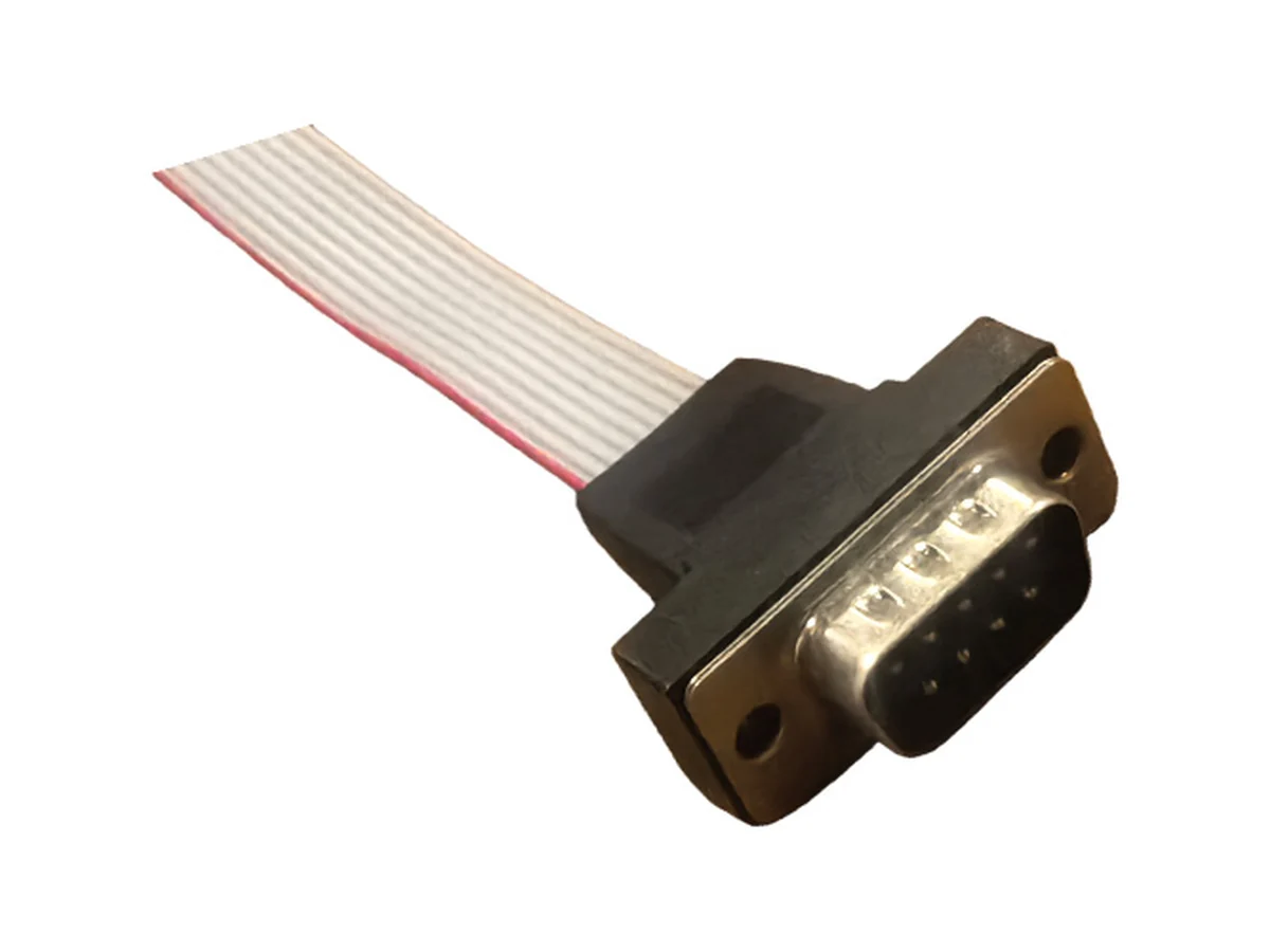
An RS232 cable might work perfectly while sitting on your quiet test bench. Yet, it inexplicably fails the moment a heavy machine starts running on the factory floor. Fixing this frustrating issue requires a very careful, step-by-step approach. You have to compare the exact software configuration. You must look closely at the physical connections. And importantly, you need to study the installed electrical environment.
Sometimes, you might notice a specific timing pattern related to a heavy motor starting up. This pattern is a great clue. However, it does not automatically prove that the cable shield is the true culprit. To figure this out properly, you need to keep a known-working reference lead close by. Then, you should change just one single factor at a time.
Intermittent faults drive maintenance teams absolutely crazy. Why? Because a standard electrical continuity check often passes with flying colors right after the equipment comes to a halt. Then, normal production restarts. Maybe a tiny connector shifts slightly due to vibration. Or perhaps a large drive switches on nearby. Suddenly, the critical data messages vanish all over again. If you get frustrated and replace several different parts at the exact same time, you might actually restore the communication link. But doing so will never tell you which specific change actually fixed the underlying problem.
For equipment builders, the ultimate goal is simple. Purchasing teams want the exact same thing. They need to turn that vague, intermittent symptom into a crystal-clear cable requirement. They also desperately need a highly repeatable acceptance check. The practical method detailed below keeps your true electrical diagnosis totally separate from those empty marketing claims about “industrial-grade” construction.
What Evidence Should You Capture Before Changing the Cable?
Before you tear out the old wiring in a panic, stop and document the situation. Start by looking at both the working and the failing conditions. Write down the specific device models involved. Note the exact software settings. Record the cable identification details, the physical routing path, and the specific operating event that triggers the communication drop. A highly detailed, timestamped event log is worth far more than a dozen vague operator complaints saying the link is acting unstable.
Keep configuration and protocol in view
Always verify the baud rate first. Check the data format. Look at the flow control settings on both ends of the connection. You also need to confirm that the interface is genuinely RS232. A physically similar D-sub connector can easily carry a completely different electrical interface, like RS422 or RS485. Always check the official equipment documents to be sure. Never use the mere shape of a connector as solid proof of the protocol.
If you can get it, hold onto the actual error message. Save the digital communication log. Keep any measured signal evidence you gathered from qualified diagnostic work. You must distinguish between entirely missing messages and jumbled, corrupted data. Also, figure out if a device has simply stopped responding altogether. These distinct symptoms often lead to very different troubleshooting paths.
For standard COM and I/O connections, you should choose the terminal interface, the wire type, and the connection map as one combined, unified package. Straight-through arrangements do one specific job. Crossed configurations serve completely different equipment connection needs. Furthermore, the available installation space and the tight internal routing paths heavily affect your final assembly selection. Always confirm the required pin map by looking directly at both device interfaces. Do not just rely on the basic connector gender. Likewise, you should ignore any vague, generalized descriptions printed on the wire jacket.
Identify the exact assembly
Make sure you record the entire pin map. Note the exact connector orientation. Write down the specific revision number of the wire. Don’t forget to include any modular adapters. List any extension leads that are plugged into the circuit, too. An RS232 cable purchased under the exact same general product description can actually differ wildly from batch to batch. It might feature completely different handshake conductors. It could have totally different shell connections inside the housing.
You should leverage LUONYX’s custom cable service for this exact step. Their team can help you discuss the complete assembly in deep technical detail. Make sure you attach both equipment interface drawings when you reach out to them. Avoid submitting a lazy purchase description. A request that only gives the connector gender and the overall length is usually a recipe for disaster on the production floor.
Is the Fault Triggered by Movement or by Electrical Activity?
You absolutely must separate these two specific conditions. Do this before you try to pick a permanent fix. Heavy machinery can easily introduce physical, mechanical movement. At the exact same time, it can generate severe electrical interference.
Compare physical conditions safely
First, make sure the equipment is fully isolated and powered down. Always follow your site’s responsible safety lock-out procedure. Then, physically inspect the seating. Look closely at the locking screws on the hood. Check the internal terminal retention. Examine the strain relief points for damage. Look for a wire that is pulled way too tight at the connector shell. See if it is bent sharply around a harsh metal exit point. Please, do not stick a metal probe into live terminals. Never handle a fully operating machine just to try and reproduce a rare fault.
If your facility allows it, get a qualified technician to help you out. They can swap and compare the currently installed wire with a known-good reference wire. This reference piece must have the exact correct pinout. During this test, keep the software settings completely unchanged. Keep the overall equipment state exactly the same. Record whether the communication fault follows the physical wire itself. Or, see if the glitch stays firmly rooted in the permanent machine installation.
Loose crimps cause major headaches. Oxidized terminals create terrible weak links. Deformed contacts can easily produce incredibly intermittent signals. Bad wire preparation will ruin your day. Improper assembly at the factory can leave a tiny copper conductor poorly retained. When physical movement changes the communication status, check the connection physically. Inspect the terminal seating. Measure the contact resistance with a proper meter. Look for harsh mechanical strain at the connection point. Do all of this before you blindly assume the outer shield material is the wrong type. Any correction you make should directly address the physical connection defect you actually observed with your own eyes.
Treat operating events as clues
Write down if the errors happen at the exact same time as a drive start. Note if they only happen during heavy mechanical braking. See if an industrial heater switching on causes a signal drop. Check if the movement of a dynamic, rolling cable carrier triggers the glitch. A repeated, highly predictable event can help narrow down your investigation immensely. However, mere correlation alone does not firmly identify the specific coupling path. It also does not magically rule out a failing power supply at one of the connected devices.
Let’s look at a practical example. Suppose a temporary reference lead works perfectly. But, it only works when it is routed far away from a giant motor drive wire. That is strong evidence. It shows that the physical routing path really matters under those specific tested conditions. But wait. It does not prove that the original inner conductor is physically broken. It also doesn’t establish some universal, magic separation distance for every single wire in the factory.
What Does a Shielded Cable Actually Need?
A shiny metal layer is just one small piece of a good shielding strategy. How it is physically terminated matters immensely. Its unique relationship to the overall equipment grounding design matters just as much.
Confirm the shield connection design
Ask the manufacturer for the specified foil construction details. Ask about the braid density. Request info on the internal drain wire arrangement. Find out about the specific connections tying the shield to the connector shell. Look into the designated termination spots on the board. Now, check if those exact connections truly exist in the delivered batch in front of you. Never, ever use the outer shield as a cheap substitute for a mandatory internal signal reference conductor.
Shielded COM/I/O builds typically use a wrapping layer of thin aluminum foil. Alternatively, they might use a tough tinned-copper braid. Sometimes they use a combination of both. If the shield gets damaged, electrical noise problems arise quickly. If the physical coverage is incomplete, interference gets in. If there is a weak physical connection to its final termination point, the intended protection drops significantly. The total length of the wire matters. The specific inner core wire selection is vital. The harsh environmental conditions are also a crucial factor. All of these elements belong in the exact same specification document. Making these choices on paper does not magically guarantee identical interference blocking for every single assembly or factory installation.
How Can the Fix Become a Production Requirement?
Eventually, your careful, controlled comparison will identify a genuinely useful correction. Once it does, you must write that exact fix directly into the official engineering drawing. Add it to the standard factory inspection plan. If you skip this critical step, your very next purchase order will likely recreate the exact same frustrating uncertainty all over again.
Define checks that match the failure
If you found a physical connection fault, specify a strict pin-to-pin continuity test on the drawing. Mandate the required shell connections. Demand specific shield ties. Force the vendor to perform physical terminal retention checks. If your problem was ultimately a routing concern, define the precise installation path clearly. Specify the exact restraint points along the frame. If the wire fails due to repeated robotic motion, request hard testing evidence that matches that exact required motion profile. A wire that just boasts “ordinary flexibility” does not prove it is actually suitable for a brutal, continuous-flex industrial environment.
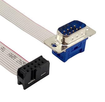
LUONYX offers fantastic OEM manufacturing services based directly on a customer-supplied design. They also do extensive ODM development starting straight from raw customer requirements. Their deep collaboration process includes a rigorous technical review step. It includes precise, transparent quotation stages. They do thorough, real-world sample testing. They strictly require formal approval before they ever move forward to scalable, mass production. Because of this solid framework, careful buyers can carry their annoying, historic fault records straight into a heavily defined custom build brief. They can use this brief for the sample review process. As a result, any unresolved pin map issues or tricky installation questions get spotted well before the final approval ever happens.
Take some time to review LUONYX’s impressive manufacturing background. Go ahead and request a thorough wire review. When you do, hand them the detailed event log you created. Give them the electrical equipment drawings. Provide the known-good reference sample details. Make sure you include any lingering, unresolved technical questions. This process ensures everything can be rigorously checked before you ever sign off on approving a large replacement batch.
Häufig gestellte Fragen
Q1: Does a passed continuity test rule out a deeper cable problem?
A1: No, it absolutely does not. It only confirms that the tested copper connections are making adequate physical contact under that specific, quiet testing condition. It may completely fail to reveal a highly intermittent contact point that only separates under vibration.
Q2: Will using a thicker, heavier shield always solve my annoying communication errors?
A2: No, it rarely works like magic. You must carefully check the pinout first. Verify the specific device software configuration. Look at the connector terminations closely. Check the physical routing near power lines. Thoroughly review the facility’s entire grounding design. The actual electrical interference path might be totally different than you assume.
Q3: What specific details should accompany a new replacement cable enquiry?
A3: You need to provide a lot of robust data to get a good result. Supply both of the actual device interface drawings. Give the manufacturer the complete, verified pin map. State the exact required physical wire length. Describe the intended installation route through the machine. Detail the harsh operating environment it will live in daily.